ID Code Box Power Source Circuit
ENGINE IMMOBILISER: ENGINE IMMOBILISER SYSTEM (w/ Smart Key System): ID Code Box Power Source Circuit
ID Code Box Power Source Circuit
DESCRIPTION
This circuit provides power to operate the ID code box.
WIRING DIAGRAM
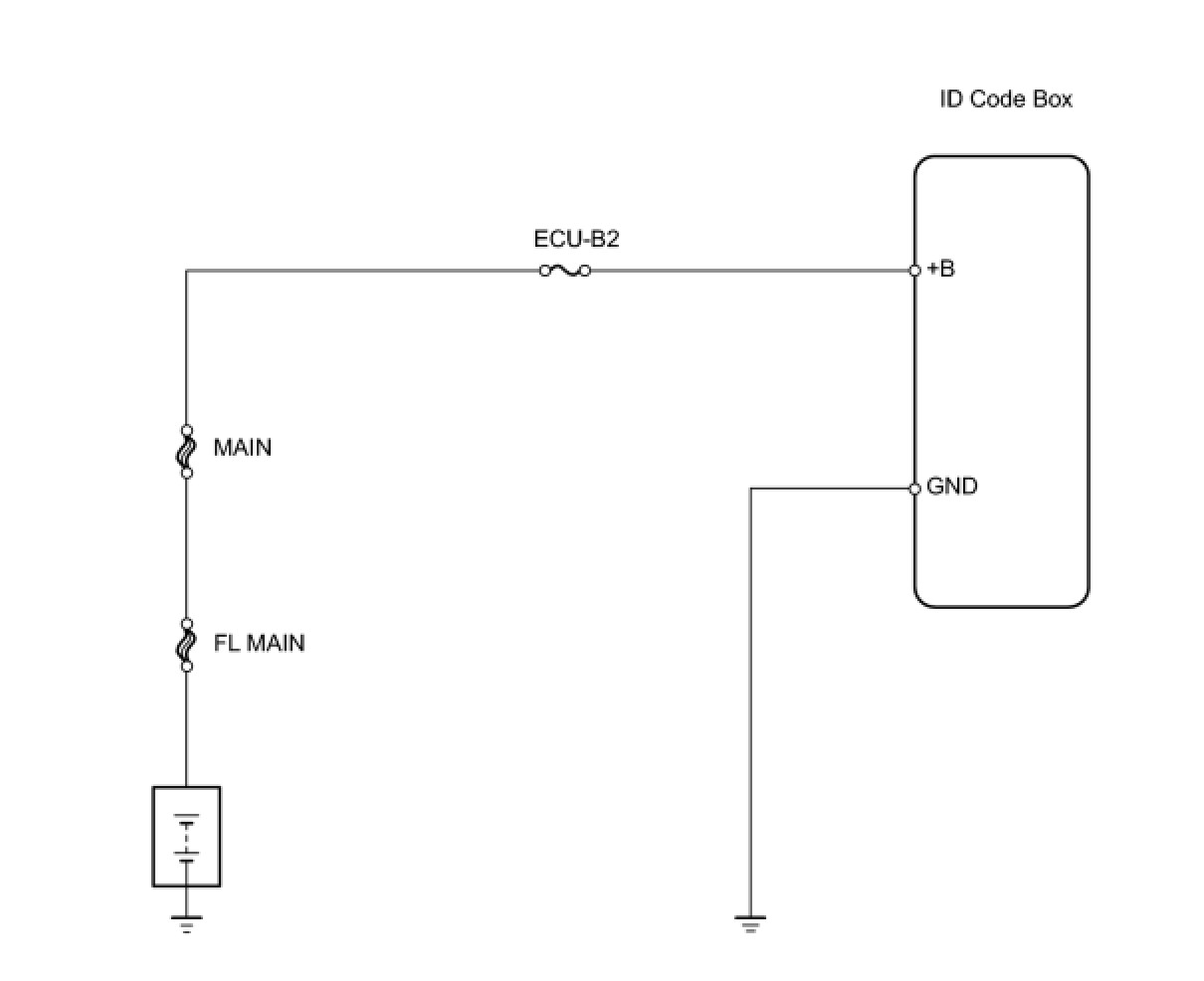
INSPECTION PROCEDURE
PROCEDURE
1. INSPECT FUSE (ECU-B)
(a) Remove the ECU-B2 fuse from the engine room No. 2 relay block.
(b) Measure the resistance of the fuse.
Standard Resistance:
Below 1 Ohms
NG -- REPLACE FUSE
OK -- Continue to next step.
2. CHECK HARNESS AND CONNECTOR (ID CODE BOX - BATTERY AND BODY GROUND)
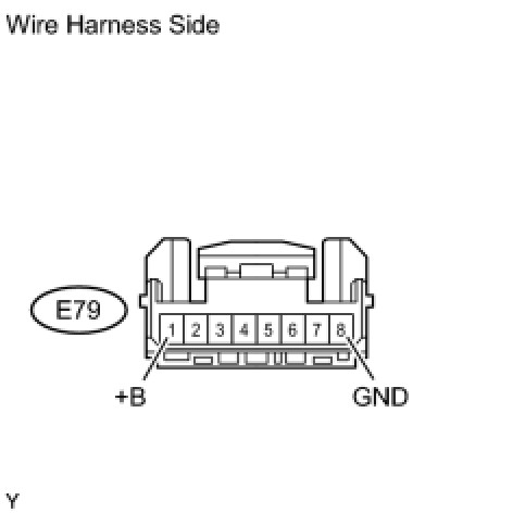
(a) Disconnect the E79 box connector.
(b) Measure the resistance and voltage of the wire harness side connector.
Standard Resistance:

Standard Voltage:

NG -- REPAIR OR REPLACE HARNESS OR CONNECTOR
OK -- PROCEED TO NEXT CIRCUIT INSPECTION SHOWN IN PROBLEM SYMPTOMS TABLE