Memory Switch Circuit
MIRROR: POWER MIRROR CONTROL SYSTEM (w/ Memory): Memory Switch Circuit
Memory Switch Circuit
DESCRIPTION
When the seat memory switch M1 or M2 is pressed, the position control ECU & switch (Seat ECU) transmits a signal of the memorized mirror position to the outer mirror control ECU. Then, the outer mirror control ECU drives the mirror motor.
HINT: The power mirror control system is a part of the multiplex communication system. This system features shared communication wiring that reduces the wiring complexity of the communication lines. The first step in any repair is to confirm the proper operation of the communication system. Proceed with troubleshooting after the communication has been verified (See the Multiplex Communication System) Initial Inspection and Diagnostic Overview.
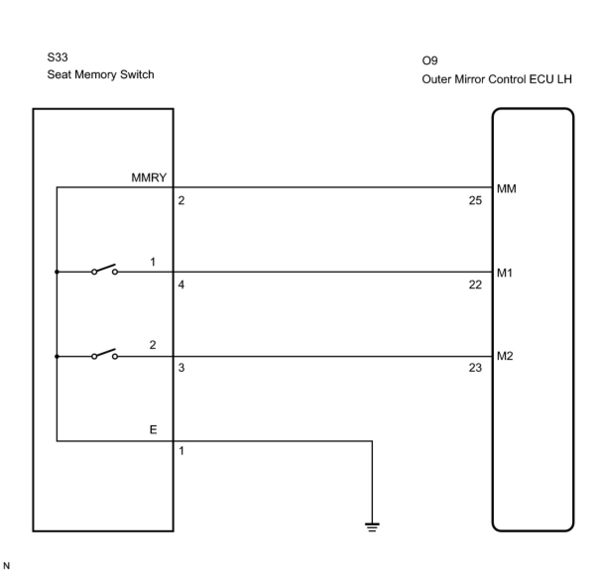
WIRING DIAGRAM
INSPECTION PROCEDURE
PROCEDURE
1. READ VALUE USING TECHSTREAM
(a) Connect Techstream to the DLC3.
(b) Ignition switch on.
(c) Check the DATA LIST for proper function of the seat memory switch.
Driver Seat:
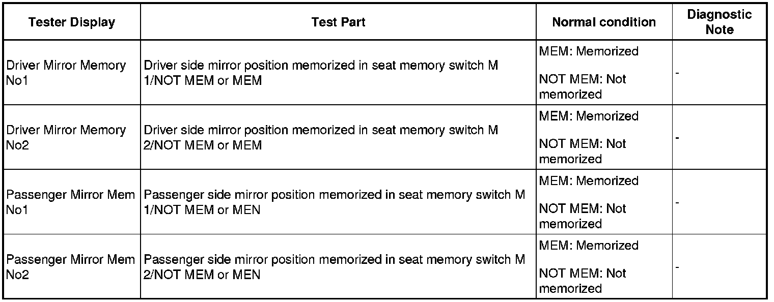
OK:
Tester displayed MEM.
OK -- PROCEED TO NEXT CIRCUIT INSPECTION SHOWN IN PROBLEM SYMPTOMS TABLE
NG -- Continue to next step.
2. INSPECT SEAT MEMORY SWITCH
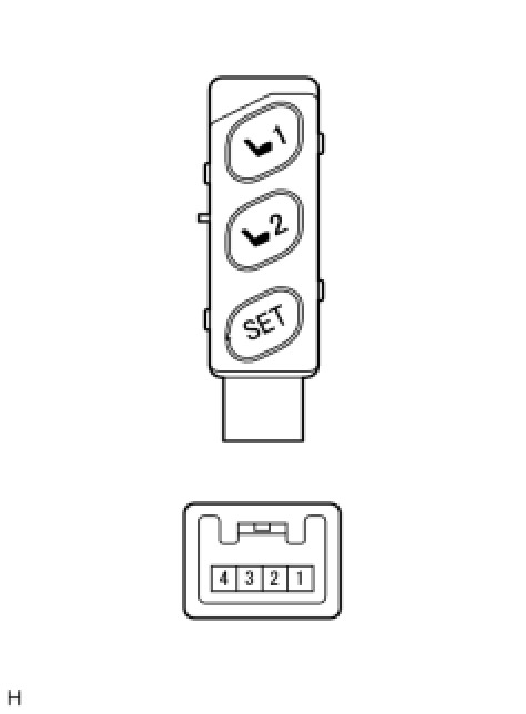
(a) Remove the seat memory switch.
(b) Measure the resistance according to the value(s) in the table below when the switch is operated.
Standard resistance:
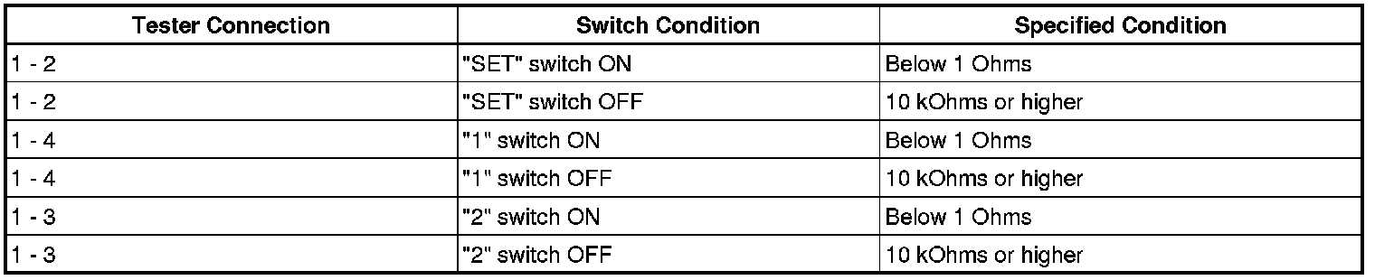
NG -- REPLACE SEAT MEMORY SWITCH
OK -- Continue to next step.
3. CHECK HARNESS AND CONNECTOR (SEAT MEMORY SWITCH - OUTER MIRROR CONTROL ECU)
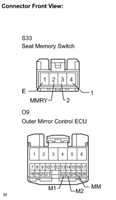
(a) Disconnect the S33 switch connector.
(b) Disconnect the O9 ECU connector.
(c) Measure the resistance according to the value(s) in the table below.
Resistance:
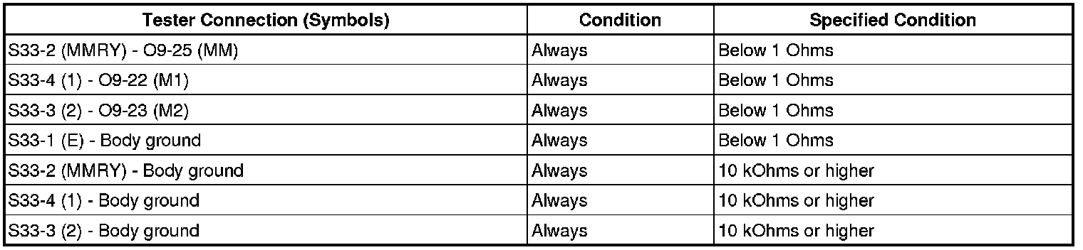
NG -- REPAIR OR REPLACE HARNESS OR CONNECTOR
OK -- REPLACE OUTER MIRROR CONTROL ECU