VC Output Circuit
1GR-FE ENGINE CONTROL SYSTEM: SFI SYSTEM: VC Output Circuit
VC Output Circuit
DESCRIPTION
The ECM constantly generates 5 V power from the battery voltages supplied to the +B (BATT) terminal to operate the microprocessor. The ECM also provides this power to the sensors through the VC output circuit.
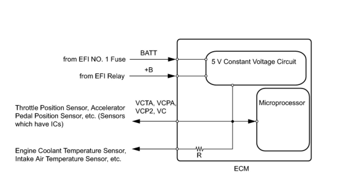
When the VC circuit is short-circuited, the microprocessor in the ECM and sensors that are supplied with power through the VC circuit are inactivated because the power is not supplied from the VC circuit. Under this condition, the system does not start up and the MIL does not illuminate even if the system malfunctions.
HINT: Under normal conditions, the MIL is illuminated for several seconds when the ignition switch is first turned ON. The MIL goes off when the engine is started.
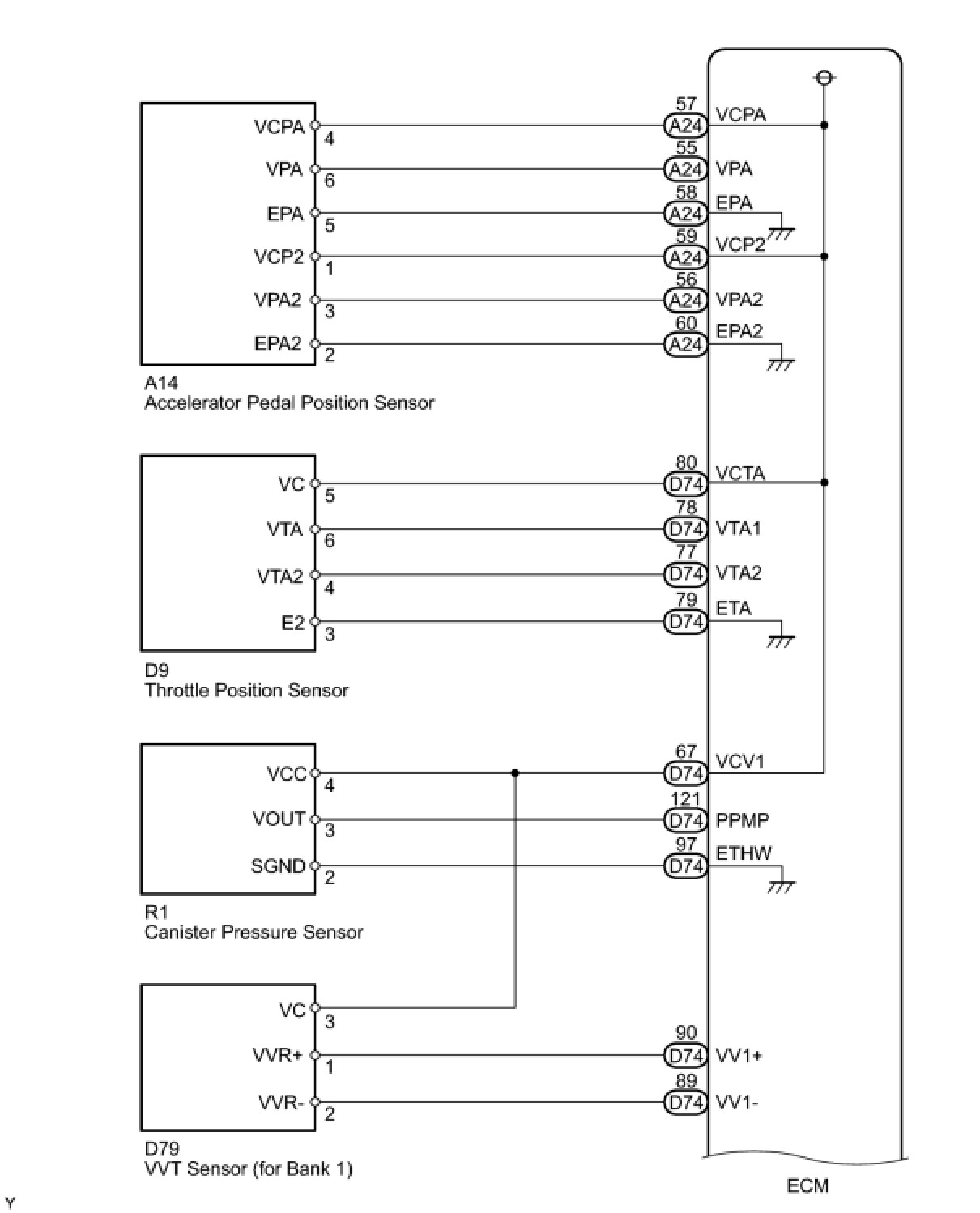
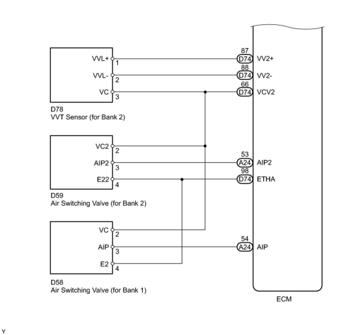
WIRING DIAGRAM
INSPECTION PROCEDURE
PROCEDURE
1. CHECK MIL
(a) Check that the Malfunction Indicator Lamp (MIL) lights up when turning the ignition switch ON.
Result:

A -- SYSTEM OK
B -- Continue to next step.
2. CHECK COMMUNICATION BETWEEN TECHSTREAM AND ECM
(a) Connect the Techstream to the DLC3.
(b) Turn the ignition switch ON and Techstream ON.
(c) Check the communication between the Techstream and ECM.
Result:

A -- GO TO MIL CIRCUIT
B -- Continue to next step.
3. CHECK MIL (THROTTLE BODY)
(a) Disconnect the throttle body connector.
(b) Turn the ignition switch ON.
(c) Check the MIL.
Result:

(d) Reconnect the throttle body connector.
A -- REPLACE THROTTLE BODY ASSEMBLY
B -- Continue to next step.
4. CHECK MIL (ACCELERATOR PEDAL POSITION SENSOR)
(a) Disconnect the accelerator pedal position sensor connector.
(b) Turn the ignition switch ON.
(c) Check the MIL.
Result:

(d) Reconnect the accelerator pedal position sensor connector.
A -- REPLACE ACCELERATOR PEDAL ASSEMBLY
B -- Continue to next step.
5. CHECK MIL (PRESSURE SENSOR [BANK 1])
(a) Disconnect the air switching valve (bank 1).
(b) Turn the ignition switch ON.
(c) Check the MIL.
Result:

(d) Reconnect the air switching valve (bank 1).
A -- REPLACE AIR SWITCHING VALVE
B -- Continue to next step.
6. CHECK MIL (PRESSURE SENSOR [BANK 2])
(a) Disconnect the air switching valve (bank 2).
(b) Turn the ignition switch ON.
(c) Check the MIL.
Result:

(d) Reconnect the air switching valve (bank 2).
A -- REPLACE AIR SWITCHING VALVE
B -- Continue to next step.
7. CHECK MIL (CANISTER PUMP MODULE)
(a) Disconnect the canister pump module connector.
(b) Turn the ignition switch ON.
(c) Check the MIL.
Result:

(d) Reconnect the canister pump module connector.
A -- REPLACE CANISTER ASSEMBLY
B -- Continue to next step.
8. PERFORM ACTIVE TEST USING MIL (VVT SENSOR [BANK 1])
(a) Disconnect the air cleaner assembly with element.
(b) Disconnect the VVT sensor (bank 1) connector.
(c) Turn the ignition switch ON.
(d) Check the MIL.
Result:

(e) Reconnect the VVT sensor (bank 1).
A -- REPLACE VVT SENSOR (BANK 1)
B -- Continue to next step.
9. CHECK MIL (VVT SENSOR [BANK 2])
(a) Disconnect the VVT sensor (bank 2) connector.
(b) Turn the ignition switch ON.
(c) Check the MIL.
Result:

(d) Reconnect the VVT sensor (bank 2) connector.
A -- REPLACE VVT SENSOR (BANK 2)
B -- Continue to next step.
10. CHECK HARNESS AND CONNECTOR
(a) Disconnect the throttle body connector.
(b) Disconnect the accelerator pedal position sensor connector.
(c) Disconnect the air switching valve (bank 1).
(d) Disconnect the air switching valve (bank 2).
(e) Disconnect the canister pump module connector.
(f) Disconnect the VVT sensor (bank 1).
(g) Disconnect the VVT sensor (bank 2).
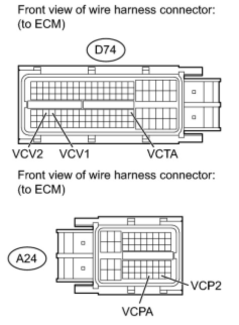
(h) Disconnect the A24 and D74 ECM connectors.
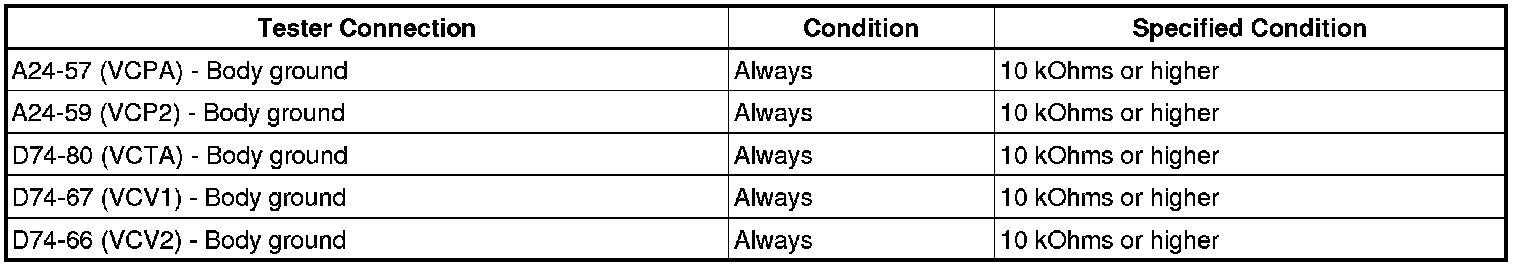
(i) Measure the resistance according to the value(s) in the table below.
Standard resistance (Check for short):
(j) Reconnect the ECM connectors.
(k) Reconnect the canister pump module connector.
(l) Reconnect the throttle body connector.
(m) Reconnect the accelerator pedal position sensor connector.
(n) Reconnect the air switching valve (bank 1).
(o) Reconnect the air switching valve (bank 2).
(p) Reconnect the VVT sensor (bank 1) connector.
(q) Reconnect the VVT sensor (bank 2) connector.
NG -- REPAIR OR REPLACE HARNESS OR CONNECTOR
OK -- REPLACE ECM