Installation
1GR-FE EMISSION CONTROL: AIR SWITCHING VALVE: INSTALLATION
INSTALLATION
1. INSTALL AIR SWITCHING VALVE ASSEMBLY
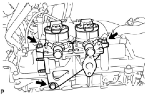
(a) Install the air switching valve with the bolt and 2 nuts.
Torque: 19 Nm (194 kgf-cm, 14 ft-lbf)
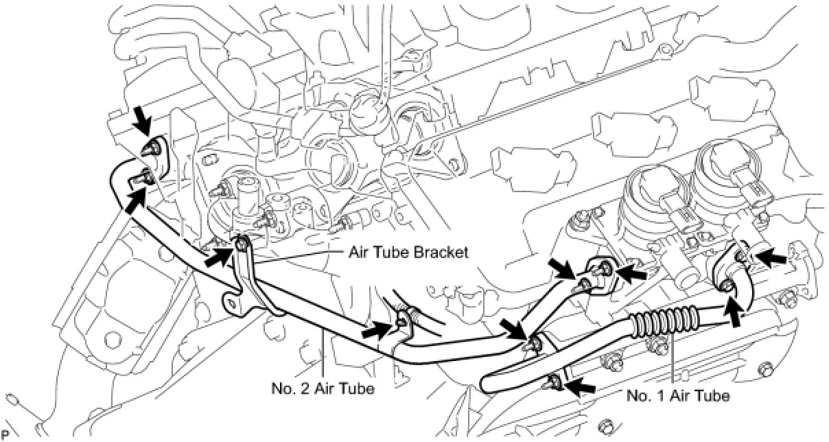
2. CONNECT NO. 2 AIR TUBE
(a) Connect the No. 2 air tube.
(1) Temporarily install a new gasket and the No. 2 air tube to the air switching valve side with the 2 nuts. Then temporarily install a new gasket and the No. 2 air tube to the exhaust manifold side with the 2 nuts.
(2) Temporarily install the No. 2 air tube bracket to the rear water by-pass joint with the bolt.
(3) Tighten the bolt and 4 nuts.
Torque: 10 Nm (102 kgf-cm, 7 ft-lbf)
(4) Connect the wire harness clamp.
3. INSTALL NO. 1 AIR TUBE
(a) Install the No. 1 air tube.
(1) Temporarily install a new gasket and the No. 1 air tube to the exhaust manifold side with the 2 nuts.
(2) Install a new gasket and the No. 1 air tube to the air switching valve side with the 2 bolts.
Torque: 10 Nm (102 kgf-cm, 7 ft-lbf)
(3) Tighten the 2 nuts on the exhaust manifold side.
Torque: 10 Nm (102 kgf-cm, 7 ft-lbf)
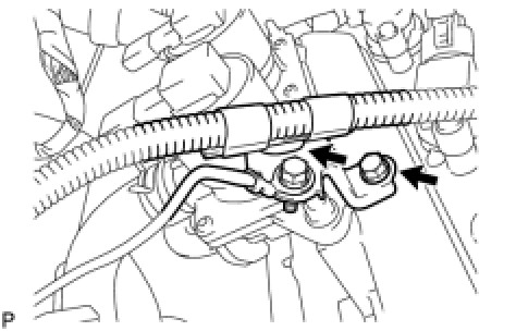
4. INSTALL AIR TUBE
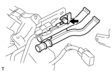
(a) Install the air tube with the bolt.
Torque: 8.0 Nm (82 kgf-cm, 71 in-lbf)
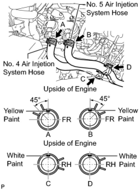
5. INSTALL NO. 4 AIR INJECTION SYSTEM HOSE
(a) Install the air injection system hose and the 2 clamps as shown in the illustration.
6. INSTALL NO. 5 AIR INJECTION SYSTEM HOSE
(a) Install the air injection system hose and the 2 clamps as shown in the illustration.
(b) Connect the wire harness bracket with the bolt and attach the wire harness clamp.
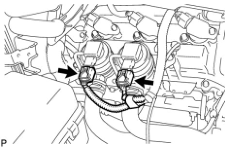
(c) Connect the 2 air pump connectors.
7. CONNECT NO. 2 AIR INJECTION SYSTEM HOSE
(a) Connect the No. 2 air injection system hose to the air tube.
8. CONNECT NO. 3 AIR INJECTION SYSTEM HOSE
(a) Connect the No. 3 air injection system hose to the air tube.
9. INSTALL INTAKE AIR SURGE TANK Installation
10. INSTALL AIR CLEANER ASSEMBLY WITH ELEMENT Installation
11. INSTALL NO. 2 AIR CLEANER HOSE Installation
12. CONNECT CABLE TO NEGATIVE BATTERY TERMINAL
NOTE: Some systems need to be initialized after the cable is reconnected Repair Instruction - Initialization.
13. ADD ENGINE COOLANT Service and Repair
14. INSPECT FOR ENGINE COOLANT LEAK Testing and Inspection
15. INSTALL V-BANK COVER Installation
16. INSTALL FRONT COWL TOP OUTER PANEL SUB-ASSEMBLY Installation
17. INSTALL FRONT WIPER MOTOR AND LINK ASSEMBLY Installation
18. INSTALL NO. 1 ENGINE UNDER COVER Installation