Cylinder Head Assembly
CYLINDER HEAD SUB-ASSEMBLY LHStep 1:
Using a 10 mm bi-hexagon wrench, install and uniformly tighten the 10 cylinder head bolts with the plate washers in several steps, in the sequence shown in the illustration.
Torque 36 Nm (367 kgf-cm, 27 ft-lbf)

Step 2:
Mark each cylinder head bolt head with paint as shown in the illustration.
Tighten the cylinder head bolts another 90° in the sequence shown in step 1.
Step 3:
Tighten the cylinder head bolts an additional 90° in the sequence shown in step 1.
Check that the painted marks are now facing rearward.

Install and uniformly tighten the 2 bolts in the sequence shown in the illustration.
Torque 21 Nm (214 kgf-cm, 15 ft-lbf)
CYLINDER HEAD SUB-ASSEMBLY RH
Step 1:
Using a 10 mm bi-hexagon wrench, install and uniformly tighten the 10 cylinder head bolts with the plate washers in several steps, in the sequence shown in the illustration.
Torque 36 Nm (367 kgf-cm, 27 ft-lbf)
Step 2:
Mark each cylinder head bolt head with paint as shown in the illustration.
Tighten the cylinder head bolts another 90° in the sequence shown in step 1.
Step 3:
Tighten the cylinder head bolts an additional 90° in the sequence shown in step 1.
Check that the painting marks are now facing rearward.

Install and uniformly tighten the 2 bolts in the sequence shown in the illustration.
Torque 21 Nm (214 kgf-cm, 15 ft-lbf)
HEAD BOLT

SURFACE VARIATION

INTAKE MANIFOLD

Install and uniformly tighten the 8 bolts and 2 nuts in several steps.
Torque 21 Nm (214 kgf-cm, 15 ft-lbf)
CAMSHAFT BEARING CAP RH

Tighten the 10 bolts in the order shown in the illustration.
Torque 16 Nm (163 kgf-cm, 12 ft-lbf)
CAMSHAFT BEARING CAP LH

Tighten the 10 bolts in the order shown in the illustration.
Torque 16 Nm (163 kgf-cm, 12 ft-lbf)
CAMSHAFT TIMING GEAR
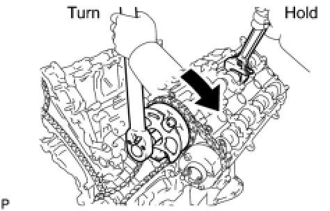
LH:
Using a wrench to hold the hexagonal portion of the No. 3 camshaft, tighten the camshaft timing gear with the bolt.
Torque 100 Nm (1020 kgf-cm, 74 ft-lbf)
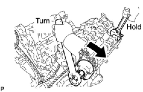
Using a wrench to hold the hexagonal portion of the No. 4 camshaft, tighten the camshaft timing exhaust gear with the bolt.
Torque 100 Nm (1020 kgf-cm, 74 ft-lbf)
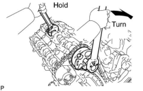
RH:
Using a wrench to hold the hexagonal portion of the No. 1 camshaft, tighten the camshaft timing gear with the bolt.
Torque 100 Nm (1020 kgf-cm, 74 ft-lbf)
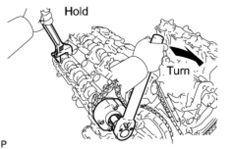
Using a wrench to hold the hexagonal portion of the No. 2 camshaft, tighten the camshaft timing exhaust gear with the bolt.
Torque 100 Nm (1020 kgf-cm, 74 ft-lbf)
EXHAUST MANIFOLD SUB-ASSEMBLY RH

Temporarily install the exhaust manifold and then uniformly tighten 8 new nuts that are not labeled A. Then tighten the new nuts labeled A in the illustration.
for nut A - Torque 10 Nm (102 kgf-cm, 7 ft-lbf)
except nut A - Torque 21 Nm (214 kgf-cm, 15 ft-lbf)
EXHAUST MANIFOLD SUB-ASSEMBLY LH

Temporarily install the exhaust manifold and then uniformly tighten 8 new nuts that are not labeled A. Then tighten the new nuts labeled A in the illustration.
for nut A - Torque 10 Nm (102 kgf-cm, 7 ft-lbf)
except nut A - Torque 21 Nm (214 kgf-cm, 15 ft-lbf)