Display Signal Circuit Between Navigation ECU and Multi-Display
NAVIGATION: NAVIGATION SYSTEM: Display Signal Circuit between Navigation ECU and Multi-display
- Display Signal Circuit between Navigation ECU and Multi-display
DESCRIPTION
This is the display signal circuit from the navigation ECU to the multi-display.
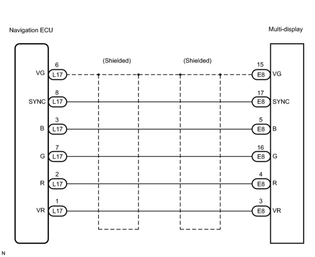
WIRING DIAGRAM
INSPECTION PROCEDURE
PROCEDURE
1. CHECK HARNESS AND CONNECTOR (NAVIGATION ECU - MULTI-DISPLAY)
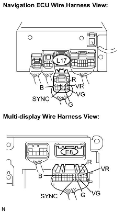
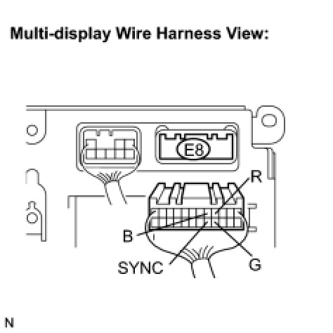
(a) Disconnect the navigation ECU connector L17 and multi-display connector E8.
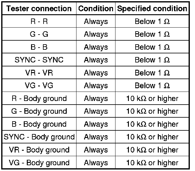
(b) Measure the resistance according to the value(s) in the table below.
Standard resistance:
NG -- REPAIR OR REPLACE HARNESS OR CONNECTOR
OK -- Continue to next step.
2. INSPECT NAVIGATION ECU (OUTPUT SIGNAL)
(a) Reconnect the navigation ECU connector L17.
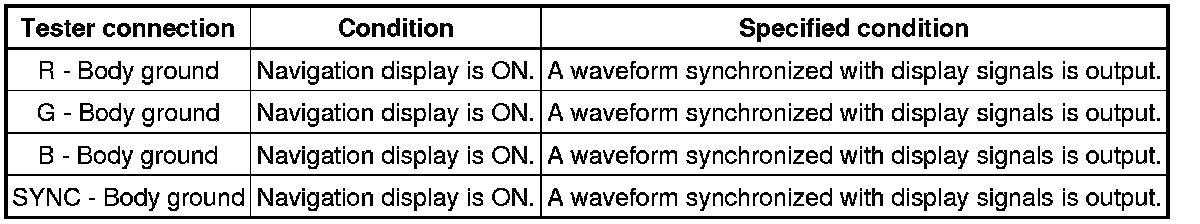
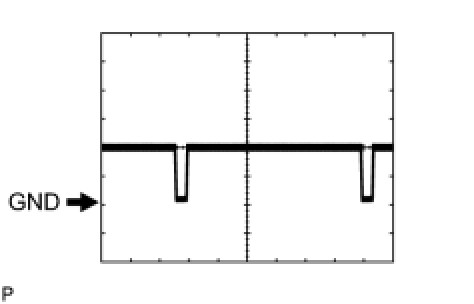
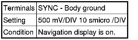
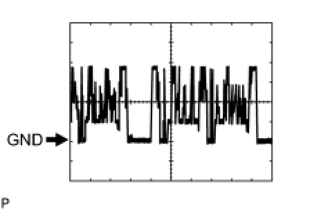
(b) Measure the waveform according to the table below.
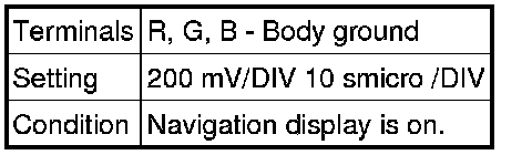
Standard:
HINT
* If SYNC signals are not being input to the multi-display due to an open circuit or other causes, the green initial screen may seem pinkish-green.
* The waveform pattern may differ from those shown in the illustrations below due to differences in oscilloscope settings. A normal navigation ECU operating condition can be determined if any waveform is output.
(1) Oscilloscope wave
(2) Oscilloscope wave
NG -- REPLACE NAVIGATION ECU
OK -- PROCEED TO NEXT CIRCUIT INSPECTION SHOWN IN PROBLEM SYMPTOMS TABLE