ECM Communication Stop Mode
CAN COMMUNICATION: CAN COMMUNICATION SYSTEM: ECM Communication Stop Mode
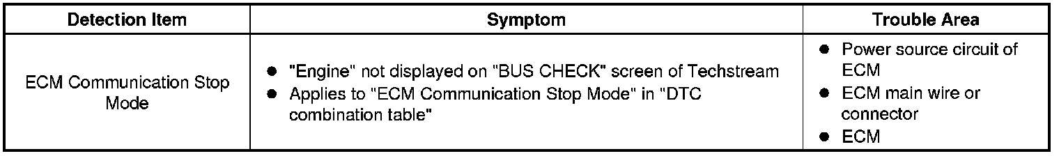
- ECM Communication Stop Mode
DESCRIPTION
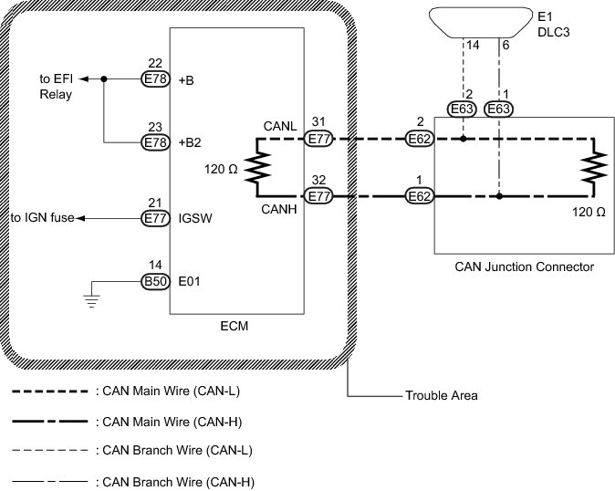
WIRING DIAGRAM
INSPECTION PROCEDURE
NOTICE:
* Turn the ignition switch off before measuring the resistances of the CAN main wire and the CAN branch wire.
* After the ignition switch is turned off, check that the key reminder warning system is not in operation.
* Before measuring the resistance, leave the vehicle as is for at least 1 minute and do not operate the ignition switch, any other switches or the doors. If doors need to be opened in order to check connectors, open the doors and leave them open.
* Inspect the fuses for circuits related to this system before performing the following inspection procedure.
HINT
Operating the ignition switch, any switches or any doors triggers related ECU and sensor communication with the CAN, which causes resistance variation.
PROCEDURE
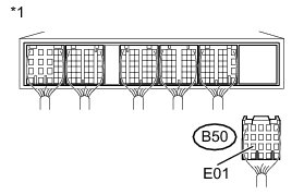
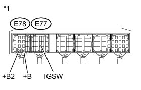
1. CHECK HARNESS AND CONNECTOR (+B2, +B, IGSW, E01)
(a) Turn the ignition switch off.
(b) Disconnect the B50 ECM connector.
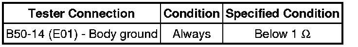
(c) Measure the resistance according to the value(s) in the table below.
Standard Resistance:
Text in Illustration

(d) Reconnect the ECM connector.
(e) Turn the ignition switch ON.
(f) Measure the voltage according to the value(s) in the table below.
Standard Voltage:
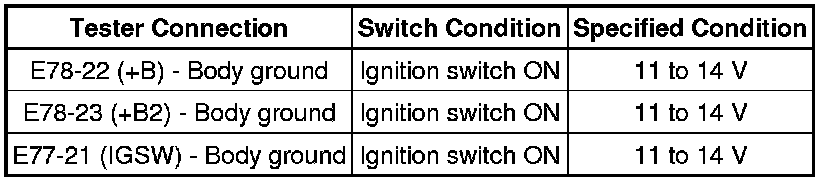
Text in Illustration
NG -- REPAIR OR REPLACE HARNESS OR CONNECTOR
OK -- REPLACE ECM Removal