Check CAN Bus Lines For Short Circuit
CAN COMMUNICATION: CAN COMMUNICATION SYSTEM: Check CAN Bus Lines for Short Circuit
- Check CAN Bus Lines for Short Circuit
DESCRIPTION
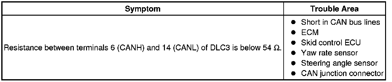
The CAN bus lines are considered to be shorted when the resistance between terminals 6 (CANH) and 14 (CANL) of the DLC3 is below 54 Ohms.
WIRING DIAGRAM

INSPECTION PROCEDURE
NOTICE:
* Turn the ignition switch off before measuring the resistances of the CAN main wire and the CAN branch wire.
* After the ignition switch is turned off, check that the key reminder warning system is not in operation.
* Before measuring the resistance, leave the vehicle as is for at least 1 minute and do not operate the ignition switch, any other switches or the doors. If doors need to be opened in order to check connectors, open the doors and leave them open.
HINT
Operating the ignition switch, any switches or any doors triggers related ECU and sensor communication with the CAN, which causes resistance variation.
PROCEDURE
1. CHECK CAN BUS LINES FOR SHORT CIRCUIT (DLC3 BRANCH WIRE)
(a) Turn the ignition switch off.
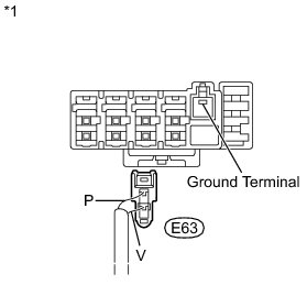
(b) Disconnect the E63 DLC3 branch wire connector.
NOTICE:
* Before disconnecting the connector, make a note of where it is connected.
* Reconnect the connector to its original position.
Text in Illustration

(c) Measure the resistance according to the value(s) in the table below.

Standard Resistance:

Text in Illustration
NG -- REPAIR OR REPLACE CAN BRANCH WIRE CONNECTED TO DLC3 (CAN-H, CAN-L)
OK -- Continue to next step.
2. CONNECT CONNECTOR
(a) Reconnect the DLC3 branch wire connector.
NEXT -- Continue to next step.
3. CHECK CAN BUS LINES FOR SHORT CIRCUIT (SKID CONTROL ECU BRANCH WIRE)
(a) Turn the ignition switch off.
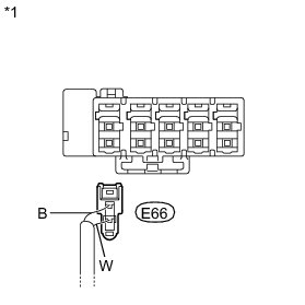
(b) Disconnect the E66 skid control ECU branch wire connector.
NOTICE:
* Before disconnecting the connector, make a note of where it is connected.
* Reconnect the connector to its original position.
Text in Illustration

(c) Measure the resistance according to the value(s) in the table below.
Standard Resistance:

Text in Illustration
NG -- CONNECT CONNECTOR
OK -- Continue to next step.
4. CONNECT CONNECTOR
(a) Reconnect the skid control ECU branch wire connector.
NEXT -- Continue to next step.
5. CHECK CAN BUS LINES FOR SHORT CIRCUIT (SKID CONTROL ECU BRANCH WIRE)
(a) Turn the ignition switch off.
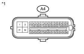
(b) Disconnect the A4 skid control ECU connector.
Text in Illustration

(c) Measure the resistance according to the value(s) in the table below.
Standard Resistance:

Text in Illustration
NG -- REPLACE CAN BRANCH WIRE CONNECTED TO SKID CONTROL ECU (CAN-H, CAN-L)
OK -- REPLACE MASTER CYLINDER SOLENOID
6. CONNECT CONNECTOR
(a) Reconnect the skid control ECU branch wire connector.
NEXT -- Continue to next step.
7. CHECK CAN BUS LINES FOR SHORT CIRCUIT (YAW RATE SENSOR BRANCH WIRE)
(a) Turn the ignition switch off.
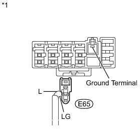
(b) Disconnect the E65 yaw rate sensor branch wire connector.
NOTICE:
* Before disconnecting the connector, make a note of where it is connected.
* Reconnect the connector to its original position.
Text in Illustration

(c) Measure the resistance according to the value(s) in the table below.
Standard Resistance:

Text in Illustration
NG -- CONNECT CONNECTOR
OK -- Continue to next step.
8. CONNECT CONNECTOR
(a) Reconnect the yaw rate sensor branch wire connector.
NEXT -- Continue to next step.
9. CHECK CAN BUS LINES FOR SHORT CIRCUIT (YAW RATE SENSOR BRANCH WIRE)
(a) Turn the ignition switch off.
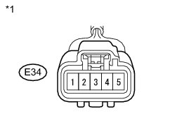
(b) Disconnect the E34 yaw rate sensor connector.
Text in Illustration

(c) Measure the resistance according to the value(s) in the table below.
Standard Resistance:

Text in Illustration
NG -- REPAIR OR REPLACE CAN BRANCH WIRE CONNECTED TO YAW RATE SENSOR (CAN-H, CAN-L)
OK -- REPLACE YAW RATE SENSOR Removal
10. CONNECT CONNECTOR
(a) Reconnect the yaw rate sensor branch wire connector.
NEXT -- Continue to next step.
11. CHECK CAN BUS LINES FOR SHORT CIRCUIT (STEERING ANGLE SENSOR BRANCH WIRE)
(a) Turn the ignition switch off.
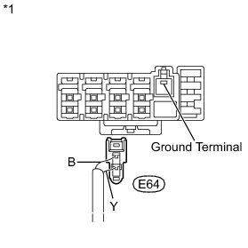
(b) Disconnect the E64 steering angle sensor branch wire connector.
NOTICE:
* Before disconnecting the connector, make a note of where it is connected.
* Reconnect the connector to its original position.
Text in Illustration

(c) Measure the resistance according to the value(s) in the table below.
Standard Resistance:

Text in Illustration
NG -- CONNECT CONNECTOR
OK -- Continue to next step.
12. CONNECT CONNECTOR
(a) Reconnect the steering angle sensor branch wire connector.
NEXT -- Continue to next step.
13. CHECK CAN BUS LINES FOR SHORT CIRCUIT (STEERING ANGLE SENSOR BRANCH WIRE)
(a) Turn the ignition switch off.
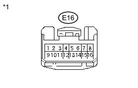
(b) Disconnect the E16 steering angle sensor connector.
Text in Illustration

(c) Measure the resistance according to the value(s) in the table below.
Standard Resistance:

Text in Illustration
NG -- REPAIR OR REPLACE CAN BRANCH WIRE CONNECTED TO STEERING ANGLE SENSOR (CAN-H, CAN-L)
OK -- REPLACE STEERING ANGLE SENSOR Removal
14. CONNECT CONNECTOR
(a) Reconnect the steering angle sensor branch wire connector.
NEXT -- Continue to next step.
15. CHECK CAN BUS LINES FOR SHORT CIRCUIT (ECM MAIN WIRE)
(a) Turn the ignition switch off.
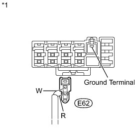
(b) Disconnect the E62 ECM main wire connector.
NOTICE:
* Before disconnecting the connector, make a note of where it is connected.
* Reconnect the connector to its original position.
Text in Illustration

(c) Measure the resistance according to the value(s) in the table below.
Standard Resistance:

Text in Illustration
NG -- REPLACE CAN JUNCTION CONNECTOR
OK -- Continue to next step.
16. CONNECT CONNECTOR
(a) Reconnect the ECM main wire connector.
NEXT -- Continue to next step.
17. CHECK CAN BUS LINES FOR SHORT CIRCUIT (ECM MAIN WIRE)
(a) Turn the ignition switch off.
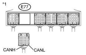
(b) Disconnect the E77 ECM connector.
Text in Illustration

(c) Measure the resistance according to the value(s) in the table below.
Standard Resistance:

Text in Illustration
NG -- REPAIR OR REPLACE CAN MAIN WIRE CONNECTED TO ECM (CAN-H, CAN-L)
OK -- REPLACE ECM Removal