Fuel Pump Control Circuit
1UR-FE ENGINE CONTROL: SFI SYSTEM: Fuel Pump Control Circuit
- Fuel Pump Control Circuit
DESCRIPTION
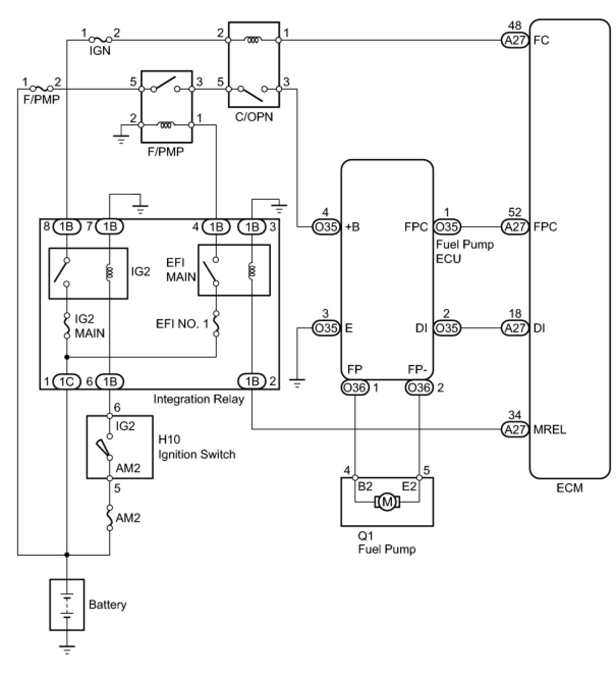
The fuel pump circuit consists of the ECM, fuel pump and fuel pump ECU (which operates the fuel pump). Based on the engine output, the ECM determines the fuel pump speed. The speed is then converted to a duty signal and sent to the fuel pump ECU. Based on the signal sent from the ECM, the fuel pump ECU adjusts the fuel pump operation speed between 3 settings.
WIRING DIAGRAM
INSPECTION PROCEDURE
This troubleshooting procedure is based on the premise that the engine can be started. If the engine cannot be started, proceed to the Problem Symptoms Table Symptom Related Diagnostic Procedures.
PROCEDURE
1. PERFORM ACTIVE TEST USING TECHSTREAM (FUEL PUMP)
(a) Connect the Techstream to the DLC3.
(b) Turn the ignition switch to ON.
(c) Turn the Techstream on.
(d) Enter the following menus: Powertrain / Engine and ECT / Active Test / Control the Fuel Pump / Speed.
(e) Check whether operating sounds can be heard while operating the relay using the Techstream.
OK:
Operating sounds can be heard from relay.
NG -- INSPECT CIRCUIT OPENING RELAY (C/OPN)
OK -- Continue to next step.
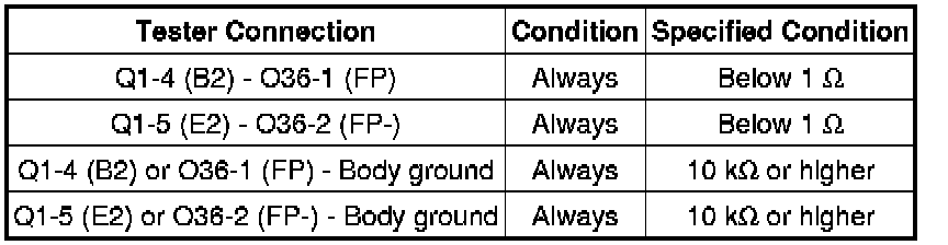
2. CHECK HARNESS AND CONNECTOR (FUEL PUMP ECU - ECM AND BODY GROUND)
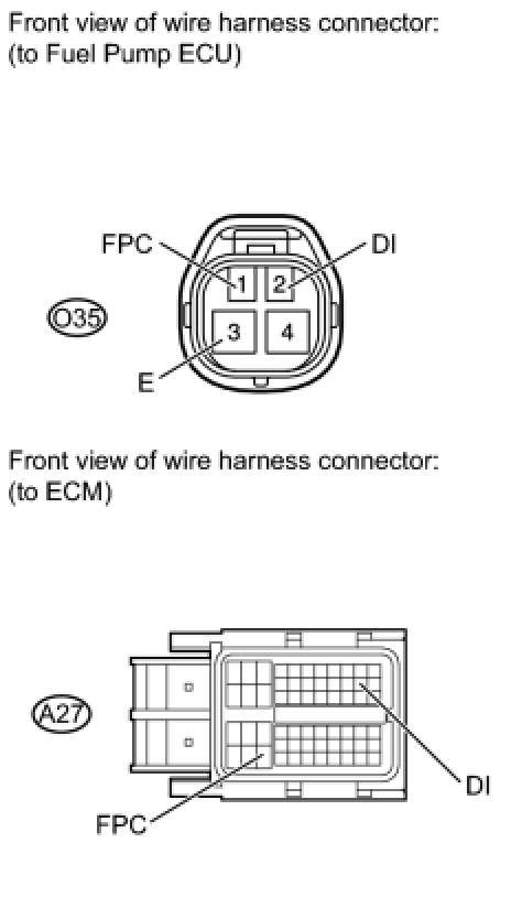
(a) Disconnect the fuel pump ECU connector.
(b) Disconnect the ECM connector.
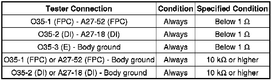
(c) Measure the resistance according to the value(s) in the table below.
Standard Resistance:
NG -- REPAIR OR REPLACE HARNESS OR CONNECTOR
OK -- Continue to next step.
3. REPLACE FUEL PUMP ECU
(a) Replace the fuel pump ECU Removal.
NEXT -- Continue to next step.
4. CONFIRM WHETHER MALFUNCTION HAS BEEN SUCCESSFULLY REPAIRED
(a) Check the fuel pump operation.
OK:
Malfunction has been repaired successfully.
NG -- REPLACE ECM Removal
OK -- END
5. INSPECT CIRCUIT OPENING RELAY (C/OPN)

(a) Remove the circuit opening relay (C/OPN) from the engine room relay block.
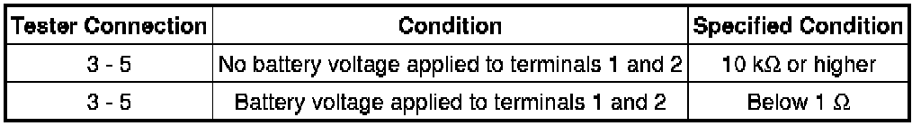
(b) Measure the resistance according to the value(s) in the table below.
Standard Resistance:
NG -- REPLACE CIRCUIT OPENING RELAY (C/OPN)
OK -- Continue to next step.
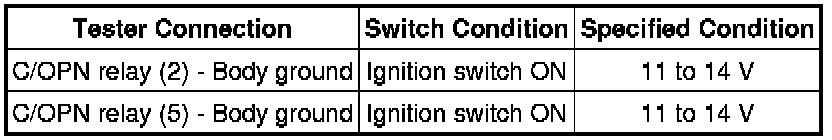
6. INSPECT CIRCUIT OPENING RELAY (POWER SOURCE VOLTAGE)

(a) Remove the circuit opening relay (C/OPN) from the engine room relay block.
(b) Turn the ignition switch to ON.
(c) Measure the voltage according to the value(s) in the table below.
Standard Voltage:
NG -- CHECK HARNESS AND CONNECTOR (CIRCUIT OPENING RELAY - FUEL PUMP RELAY AND IGN FUSE)
OK -- Continue to next step.
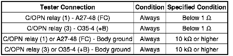
7. CHECK HARNESS AND CONNECTOR (CIRCUIT OPENING RELAY - ECM AND FUEL PUMP ECU)
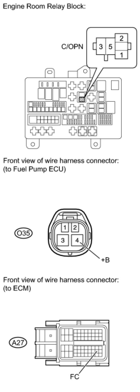
(a) Remove the circuit opening relay (C/OPN) from the engine room relay block.
(b) Disconnect the ECM connector.
(c) Disconnect the fuel pump ECU connector.
(d) Measure the resistance according to the value(s) in the table below.
Standard Resistance:
NG -- REPAIR OR REPLACE HARNESS OR CONNECTOR
OK -- Continue to next step.
8. CHECK HARNESS AND CONNECTOR (FUEL PUMP - FUEL PUMP ECU)
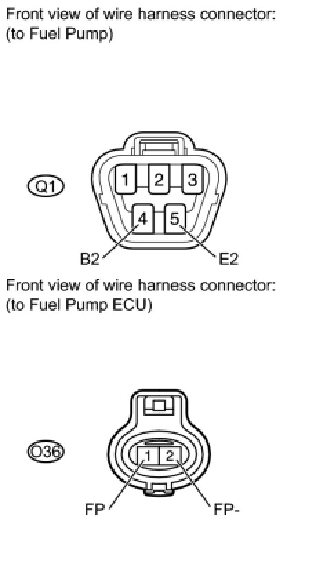
(a) Disconnect the fuel pump connector.
(b) Disconnect the fuel pump ECU connector.
(c) Measure the resistance according to the value(s) in the table below.
Standard Resistance:
NG -- REPAIR OR REPLACE HARNESS OR CONNECTOR
OK -- Continue to next step.
9. INSPECT FUEL PUMP
(a) Inspect the fuel pump Fuel Pump.
NG -- REPLACE FUEL PUMP Removal
OK -- Continue to next step.
10. CHECK HARNESS AND CONNECTOR (FUEL PUMP ECU - ECM AND BODY GROUND)

(a) Disconnect the fuel pump ECU connector.
(b) Disconnect the ECM connector.
(c) Measure the resistance according to the value(s) in the table below.
Standard Resistance:

NG -- REPAIR OR REPLACE HARNESS OR CONNECTOR
OK -- Continue to next step.
11. REPLACE FUEL PUMP ECU
(a) Replace the fuel pump ECU Removal.
NEXT -- Continue to next step.
12. CONFIRM WHETHER MALFUNCTION HAS BEEN SUCCESSFULLY REPAIRED
(a) Check the fuel pump operation.
OK:
Malfunction has been repaired successfully.
NG -- REPLACE ECM Removal
OK -- END
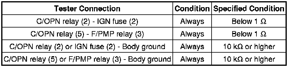
13. CHECK HARNESS AND CONNECTOR (CIRCUIT OPENING RELAY - FUEL PUMP RELAY AND IGN FUSE)
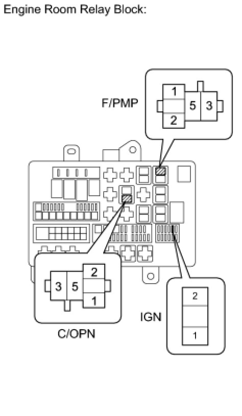
(a) Remove the circuit opening relay (C/OPN) from the engine room relay block.
(b) Remove the fuel pump relay (F/PMP) from the engine room relay block.
(c) Remove the IGN fuse from the engine room relay block.
(d) Measure the resistance according to the value(s) in the table below.
Standard Resistance:
NG -- REPAIR OR REPLACE HARNESS OR CONNECTOR
OK -- Continue to next step.
14. INSPECT FUEL PUMP RELAY (F/PMP)
(a) Remove the fuel pump relay (F/PMP) from the engine room relay block.
(b) Measure the resistance according to the value(s) in the table below.
Standard Resistance:

NG -- REPLACE FUEL PUMP RELAY (F/PMP)
OK -- Continue to next step.
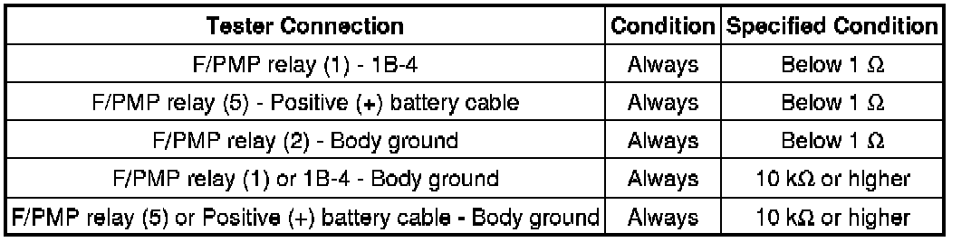
15. CHECK HARNESS AND CONNECTOR (FUEL PUMP RELAY - INTEGRATION RELAY, BATTERY AND BODY GROUND)
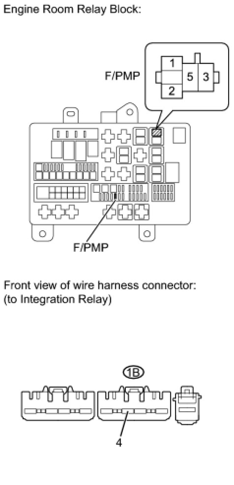
(a) Remove the F/PMP fuse from the engine room relay block.
(b) Measure the resistance according to the value(s) in the table below.
Standard Resistance:

(c) Reinstall the F/PMP fuse.
(d) Remove the fuel pump relay (F/PMP) from the engine room relay block.
(e) Remove the integration relay from the engine room relay block.
(f) Disconnect the integration relay connector.
(g) Disconnect the cable from the battery positive (+) terminal.
(h) Measure the resistance according to the value(s) in the table below.
Standard Resistance:
NG -- REPAIR OR REPLACE HARNESS OR CONNECTOR
OK -- GO TO ECM POWER SOURCE CIRCUIT Component Tests and General Diagnostics