Display Signal Circuit between Inner Rear View Mirror Assembly and Television Camera Assembly
PARK ASSIST / MONITORING: REAR VIEW MONITOR SYSTEM (w/o Navigation System): Display Signal Circuit between Inner Rear View Mirror Assembly and Television Camera Assembly
- Display Signal Circuit between Inner Rear View Mirror Assembly and Television Camera Assembly
DESCRIPTION
This is the display signal circuit of the television camera.
WIRING DIAGRAM
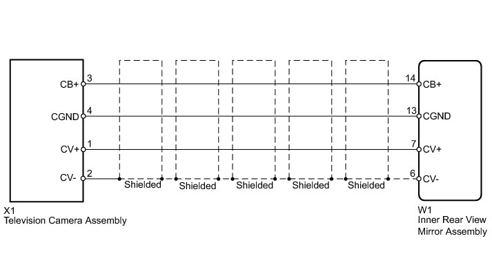
INSPECTION PROCEDURE
PROCEDURE
1. CHECK INNER REAR VIEW MIRROR ASSEMBLY
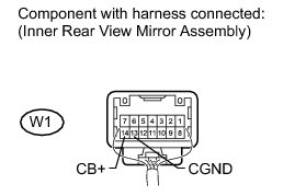
(a) Measure the voltage according to the value(s) in the table below.
Standard Voltage:

NG -- REPLACE INNER REAR VIEW MIRROR ASSEMBLY Removal
OK -- Continue to next step.
2. CHECK TELEVISION CAMERA ASSEMBLY
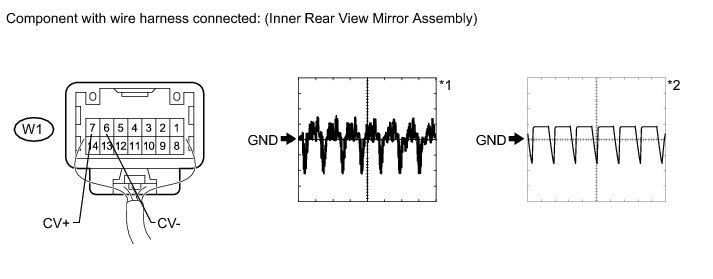
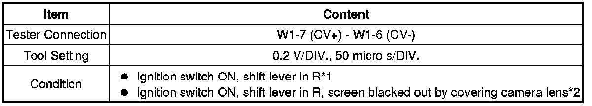
(a) Using an oscilloscope, check the waveform.
Measurement Condition
OK:
Waveform is as shown in illustration.
NG -- CHECK HARNESS AND CONNECTOR (INNER REAR VIEW MIRROR - TELEVISION CAMERA)
OK -- PROCEED TO NEXT SUSPECTED AREA SHOWN IN PROBLEM SYMPTOMS TABLE Rear View Monitor System (w/o Navigation System)
3. CHECK HARNESS AND CONNECTOR (INNER REAR VIEW MIRROR - TELEVISION CAMERA)
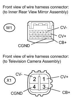
(a) Disconnect the W1 inner rear view mirror assembly connector.
(b) Disconnect the X1 television camera assembly connector.
(c) Measure the resistance according to the value(s) in the table below.
Standard Resistance:
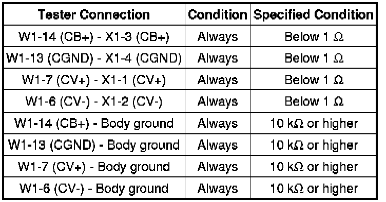
NG -- REPAIR OR REPLACE HARNESS OR CONNECTOR
OK -- REPLACE TELEVISION CAMERA ASSEMBLY Removal