Cylinder Head Assembly
CYLINDER HEAD SUB-ASSEMBLY RH (for Bank 1)The cylinder head bolts are tightened in 3 progressive steps.
Install the plate washer to the cylinder head bolt.
Step 1:
Using a 10 mm bi-hexagon wrench, install and uniformly tighten the 8 cylinder head bolts with the plate washers in several steps in the sequence shown in the illustration.
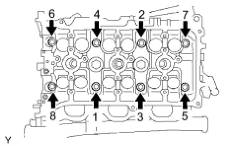
Torque 36 Nm (367 kgf-cm, 27 ft-lbf)
If any one of the cylinder head bolts does not meet the torque specification, replace the cylinder head bolt.
Step 2:
Mark the cylinder head bolt heads with paint as shown in the illustration.
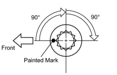
Tighten the cylinder head bolts another 90° in the sequence shown in step 1.
Step 3:
Tighten the cylinder head bolts by an additional 90° in the sequence shown in step 1.
Check that the painted marks are now facing rearward.
CYLINDER HEAD SUB-ASSEMBLY LH (for Bank 2)
The cylinder head bolts are tightened in 3 progressive steps.
Install the plate washer to the cylinder head bolt.
Step 1:
Using a 10 mm bi-hexagon wrench, install and uniformly tighten the 8 cylinder head bolts with the plate washers in several steps in the sequence shown in the illustration.
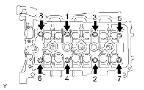
Torque 36 Nm (367 kgf-cm, 27 ft-lbf)
If any one of the cylinder head bolts does not meet the torque specification, replace the cylinder head bolt.
Step 2:
Mark the cylinder head bolt heads with paint as shown in the illustration.
Tighten the cylinder head bolts another 90° in the sequence shown in step 1.
Step 3:
Tighten the cylinder head bolts by an additional 90° in the sequence shown in step 1.
Check that the painted marks are now facing rearward.
Install the 2 bolts in the order shown in the illustration.
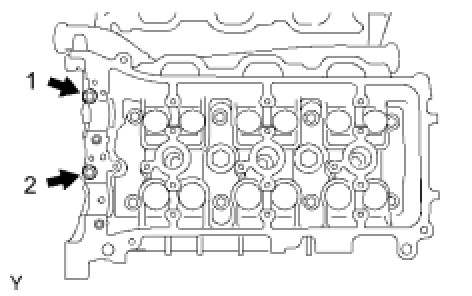
Install the 2 cylinder head bolts. Using several steps, tighten the bolts uniformly in the sequence shown in the illustration.
Torque 30 Nm (306 kgf-cm, 22 ft-lbf)
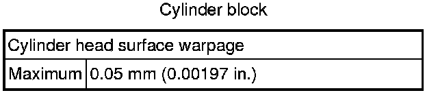
SURFACE VARIATION

CYLINDER HEAD SET BOLT
Using a vernier caliper, measure the outside thread diameter of the bolt.
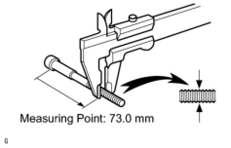
Measuring point 73.0 mm (2.87 in.)
Standard outside diameter 10.85 to 11.0 mm (0.427 to 0.433 in.)
Minimum outside diameter 10.7 mm (0.421 in.)
CAMSHAFTS
For Bank 1:
Install the camshaft.
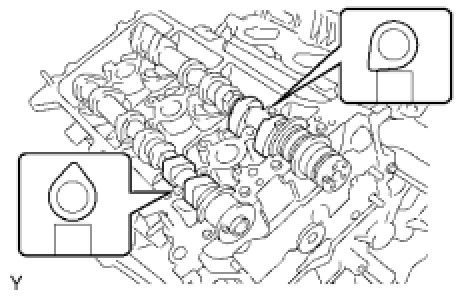
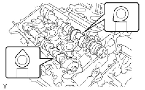
Place the 2 camshafts onto the cylinder head with the cam lobes of the No. 1 cylinder facing each direction as shown in the illustration.
Install the 8 bearing caps in their proper locations.
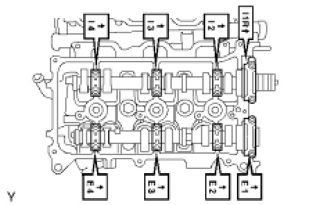
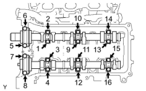
Uniformly install the 16 bolts in several steps in the order shown in the illustration.
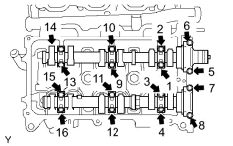
For 10 mm head - Torque 9.0 Nm (92 kgf-cm, 80 in-lbf)
For 12 mm head - Torque 24 Nm (245 kgf-cm, 18 ft-lbf)
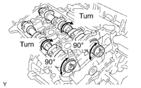
Using a wrench, turn the camshafts clockwise until the camshaft knock pin is at a position 90° to the cylinder head.
For Bank 2:
Install the camshafts.
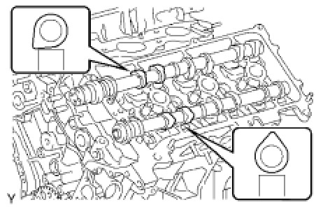
Place the 2 camshafts onto the cylinder head with the cam lobes of the No. 2 cylinder facing as shown in the illustration.
Install the 8 bearing caps in their proper locations.
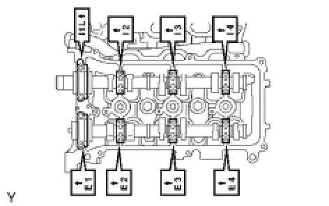
Uniformly install the 16 bolts in several steps in the order shown in the illustration.
For 10 mm head - Torque 9.0 Nm (92 kgf-cm, 80 in-lbf)
For 12 mm head - Torque 24 Nm (245 kgf-cm, 18 ft-lbf)
NO. 1 CAMSHAFT AND NO. 2 CAMSHAFT
Place the 2 camshafts onto the cylinder head with the cam lobes of the No. 1 cylinder facing each direction as shown in the illustration.
Install the 8 bearing caps in their proper locations.
Uniformly install the 16 bearing cap bolts in several steps in the order shown in the illustration.
For 10 mm head - Torque 9.0 Nm (92 kgf-cm, 80 in-lbf)
For 12 mm head - Torque 24 Nm (245 kgf-cm, 18 ft-lbf)
Using a wrench, turn the camshafts clockwise until the camshaft knock pin is at a position 90° to the cylinder head.
NO. 3 CAMSHAFT AND NO. 4 CAMSHAFT
Place the 2 camshafts onto the cylinder head with the cam lobes of the No. 2 cylinder facing each direction as shown in the illustration.
Install the 8 bearing caps in their proper locations.
Uniformly install the 16 bearing cap bolts in several steps in the order shown in the illustration.
For 10 mm head - Torque 9.0 Nm (92 kgf-cm, 80 in-lbf)
For 12 mm head - Torque 24 Nm (245 kgf-cm, 18 ft-lbf)
INTAKE MANIFOLD TORQUE & SEQUENCE Specifications
EXHAUST MANIFOLD TORQUE & SEQUENCE Specifications
CAMSHAFT GEAR/SPROCKET TORQUE Specifications