ACIS Control Circuit
3UR-FE ENGINE CONTROL SYSTEM: SFI SYSTEM: ACIS Control Circuit
- ACIS Control Circuit
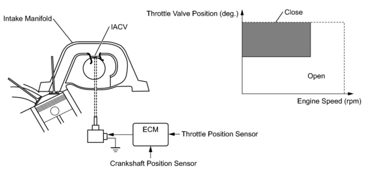
DESCRIPTION
This circuit opens and closes the Intake Air Control Valve (IACV) in response to the engine load in order to increase the intake efficiency (ACIS: Acoustic Control Induction System).
WIRING DIAGRAM

INSPECTION PROCEDURE
PROCEDURE
1. PERFORM ACTIVE TEST USING TECHSTREAM (OPERATE VSV FOR ACIS)

(a) Disconnect the vacuum hose from port F on the vacuum switching valve (for ACIS).
(b) Connect the Techstream to the DLC3.
(c) Start the engine.
(d) Enter the following menus: Powertrain / Engine and ECT / Active Test / Active the VSV for Intake Control.
(e) Operate the VSV for ACIS.
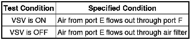
(f) Check the VSV air flow when switching the VSV.
OK:
NG -- INSPECT VACUUM SWITCHING VALVE
OK -- Continue to next step.
2. CHECK VACUUM HOSES (VACUUM SWITCHING VALVE - INTAKE AIR CONTROL VALVE, INTAKE MANIFOLD)
NG -- REPAIR OR REPLACE VACUUM HOSES
OK -- Continue to next step.
3. INSPECT INTAKE MANIFOLD (INTAKE AIR CONTROL VALVE)
(a) Inspect the intake air control valve Testing and Inspection.
NG -- REPLACE INTAKE MANIFOLD Removal
OK -- PROCEED TO NEXT CIRCUIT INSPECTION SHOWN IN PROBLEM SYMPTOMS TABLE Symptom Related Diagnostic Procedures
4. INSPECT VACUUM SWITCHING VALVE
(a) Inspect the vacuum switching valve Variable Induction Control Solenoid.
NG -- REPLACE VACUUM SWITCHING VALVE Removal
OK -- Continue to next step.
5. CHECK HARNESS AND CONNECTOR (VACUUM SWITCHING VALVE - ECM AND INTEGRATION RELAY)

(a) Remove the EFI NO. 2 fuse from the engine room relay block.
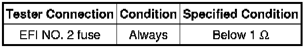
(b) Check the EFI NO. 2 fuse.
(c) Measure the resistance according to the value(s) in the table below.
Standard resistance:
(d) Reinstall the EFI NO. 2 fuse.
(e) Disconnect the D62 intake air control valve connector.
(f) Disconnect the D74 ECM connector.
(g) Remove the integration relay from the engine room relay block .
(h) Disconnect the 1B integration relay connector.
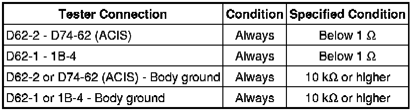
(i) Measure the resistance according to the value(s) in the table below.
Standard resistance:
NG -- REPAIR OR REPLACE HARNESS OR CONNECTOR
OK -- REPLACE ECM Removal