Sound Signal Circuit Between Stereo Component Tuner Assembly and Multi-media Interface ECU (to 12/2010)
NAVIGATION: NAVIGATION SYSTEM: Sound Signal Circuit between Stereo Component Tuner Assembly and Multi-media Interface ECU
- Sound Signal Circuit between Stereo Component Tuner Assembly and Multi-media Interface ECU
DESCRIPTION
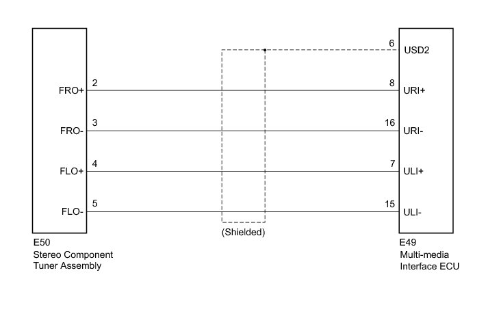
The stereo component tuner assembly sends satellite radio sound signals to the navigation receiver assembly via this circuit and the multi-media interface ECU.
The sound signal that has been sent is amplified by the stereo component amplifier assembly, and then is sent to the speakers.
If there is an open or short in the circuit, sound cannot be heard from the speakers even if there is no malfunction in the multi-media interface ECU, stereo component amplifier assembly, navigation receiver assembly or speakers.
WIRING DIAGRAM
INSPECTION PROCEDURE
NOTICE:
After replacing the stereo component tuner assembly of vehicles subscribed to pay-type satellite radio broadcasts, registration of the XM radio ID is necessary.
PROCEDURE
1. CHECK HARNESS AND CONNECTOR (MULTI-MEDIA INTERFACE ECU - STEREO COMPONENT TUNER ASSEMBLY)
(a) Disconnect the E49 multi-media interface ECU connector.
(b) Disconnect the E50 stereo component tuner assembly connector.
(c) Measure the resistance according to the value(s) in the table below.
Standard Resistance:
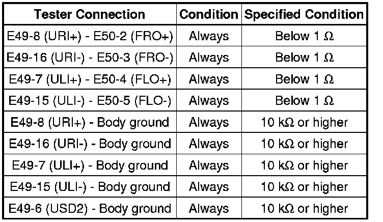
NG -- REPAIR OR REPLACE HARNESS OR CONNECTOR
OK -- Continue to next step.
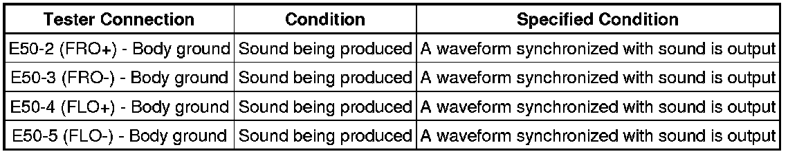
2. INSPECT STEREO COMPONENT TUNER ASSEMBLY
(a) Reconnect the E50 stereo component tuner assembly connector.
(b) Check the waveform according to the conditions in the table below.
Standard:
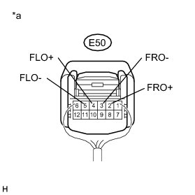
Text in Illustration
NG -- REPLACE STEREO COMPONENT TUNER ASSEMBLY Removal (to 12/2010)
OK -- PROCEED TO NEXT SUSPECTED AREA SHOWN IN PROBLEM SYMPTOMS TABLE Problem Symptoms Table (to 12/2010)