Part 2
U760E AUTOMATIC TRANSAXLE: AUTOMATIC TRANSAXLE UNIT: DISASSEMBLY - Continued
10. REMOVE TRANSMISSION VALVE BODY ASSEMBLY
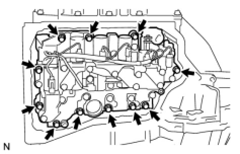
(a) Remove the 11 bolts and valve body assembly from the transaxle case.
NOTICE:
When removing the transmission valve body assembly, be careful not to allow the transmission revolution sensor and the transaxle case to interfere with each other.
11. REMOVE TRANSAXLE CASE GASKET
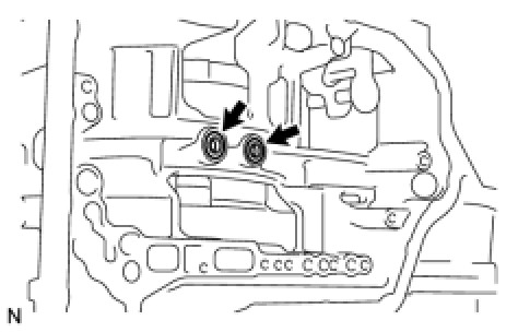
(a) Remove the 2 gaskets from the transaxle case.
12. INSPECT INPUT SHAFT SUB-ASSEMBLY Transaxle Unit
13. REMOVE REAR TRANSAXLE COVER SUB-ASSEMBLY
(a) Remove the refill plug from the rear transaxle cover sub-assembly.
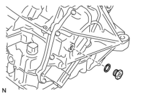
(b) Remove the gasket from the refill plug.
(c) Remove the 3 No. 1 automatic transaxle case plugs from the rear transaxle cover sub-assembly.
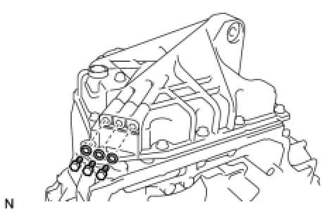
(d) Using a screwdriver, remove the 3 O-rings from the 3 No. 1 automatic transaxle case plugs.
(e) Remove the 14 bolts from the rear transaxle cover sub-assembly.
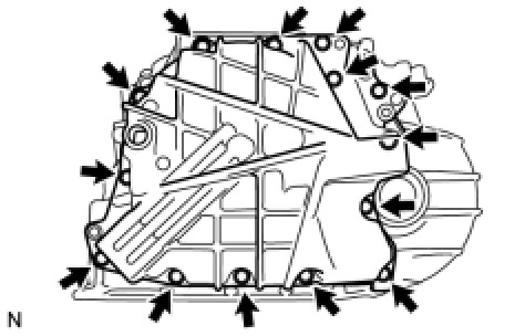
(f) Using a brass bar and hammer, tap on the circumference of the rear transaxle cover sub-assembly to remove the rear transaxle cover sub-assembly from the transaxle case.
(g) Using a screwdriver, remove the 3 O-rings from the transaxle case.
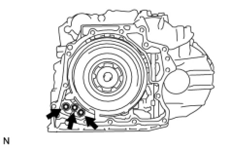
(h) Using a screwdriver, remove the 2 oil seal rings from the rear transaxle cover sub-assembly.
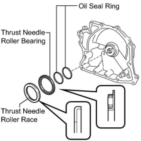
(i) Remove the thrust needle roller bearing and thrust needle roller race from the rear transaxle cover sub-assembly.
(j) Using a "TORX" wrench (T30), remove the 2 "TORX" screws and rear transaxle cover plate from the rear transaxle cover sub-assembly.
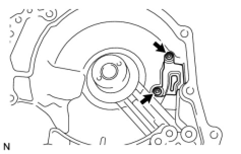
(k) Using SST, remove the needle roller bearing from the rear transaxle cover sub-assembly.
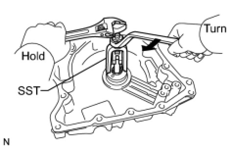
SST : 09319-60020
14. REMOVE REAR NO. 2 PLANETARY SUN GEAR THRUST NEEDLE ROLLER BEARING
(a) Remove the direct multiple disc clutch assembly from the transaxle case.
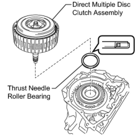
(b) Remove the rear No. 2 planetary sun gear thrust needle roller bearing from the direct multiple disc clutch assembly.
15. REMOVE REAR PLANETARY SUN GEAR THRUST NEEDLE ROLLER BEARING
(a) Using 2 screwdrivers and a hammer, tap out the snap ring from the direct multiple disc clutch assembly.
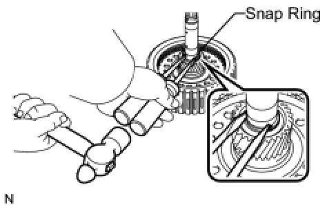
HINT
Use a piece of cloth to keep the snap ring from flying off.
(b) Remove the rear planetary sun gear assembly from the direct multiple disc clutch assembly.
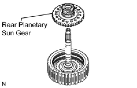
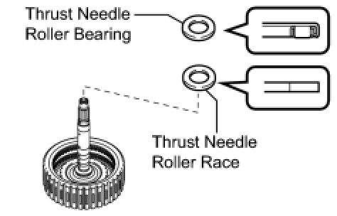
(c) Remove the rear planetary sun gear thrust needle roller bearing and thrust needle roller race from the direct multiple disc clutch assembly.
(d) Using a screwdriver, remove the O-ring from the direct multiple disc clutch assembly.
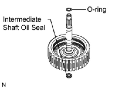
(e) Using a screwdriver, remove the intermediate shaft oil seal from the direct multiple disc clutch assembly.
16. REMOVE TRANSAXLE HOUSING
(a) Remove the 20 bolts from the transaxle housing.
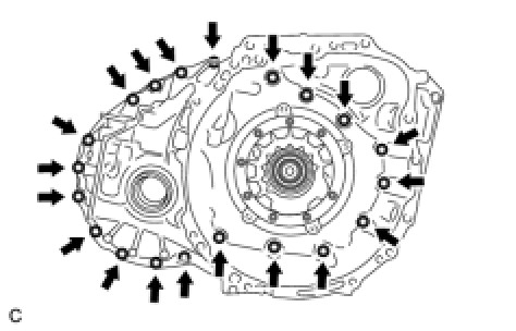
(b) Using a brass bar and hammer, tap on the circumference of the transaxle housing to remove the transaxle housing from the transaxle case.
17. REMOVE COUNTER DRIVEN GEAR FRONT TAPERED ROLLER BEARING OUTER RACE
(a) Using SST, remove the counter driven gear front tapered roller bearing outer race and shim from the transaxle housing.
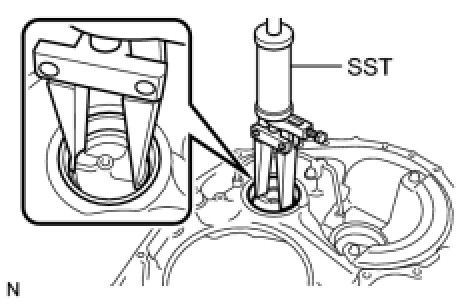
SST : 09308-00010
18. REMOVE FRONT DIFFERENTIAL CASE FRONT TAPERED ROLLER BEARING OUTER RACE Disassembly
19. REMOVE FRONT TRANSAXLE CASE OIL SEAL Disassembly
20. REMOVE DIFFERENTIAL GEAR LUBE APPLY TUBE
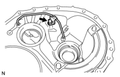
(a) Remove the bolt, clamp, and differential gear lube apply tube from the transaxle housing.
21. REMOVE TRANSAXLE HOUSING OIL SEPARATOR
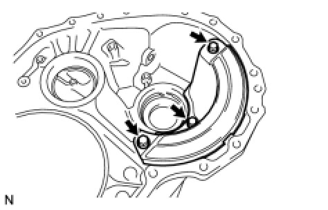
(a) Remove the 3 bolts and transaxle housing oil separator from the transaxle housing.
22. REMOVE OIL PUMP ASSEMBLY
(a) Remove the O-ring from the oil pump assembly.
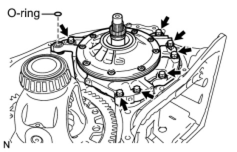
(b) Remove the 7 bolts and oil pump from the transaxle case.
(c) Remove the O-ring.
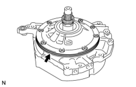
(d) Remove the thrust needle roller bearing and thrust needle roller race from the carrier lock nut.
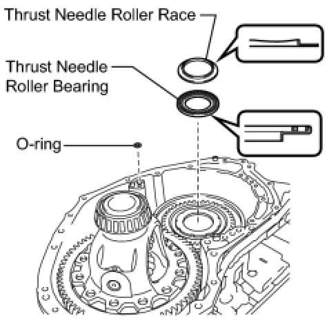
(e) Remove the O-ring from the transaxle case.
23. REMOVE NO. 3 BRAKE DISC
(a) Using a screwdriver, remove the snap ring from the oil pump assembly.
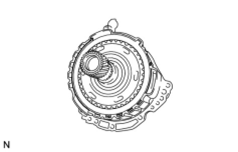
(b) Remove the 2 brake flanges, 3 brake discs, and 2 brake plates from the oil pump assembly.
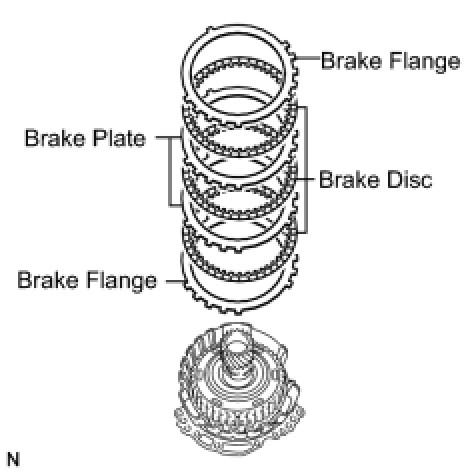
24. INSPECT NO. 3 BRAKE DISC Transaxle Unit
25. REMOVE UNDERDRIVE PLANETARY GEAR ASSEMBLY
(a) Remove the underdrive planetary gear assembly from the oil pump assembly.
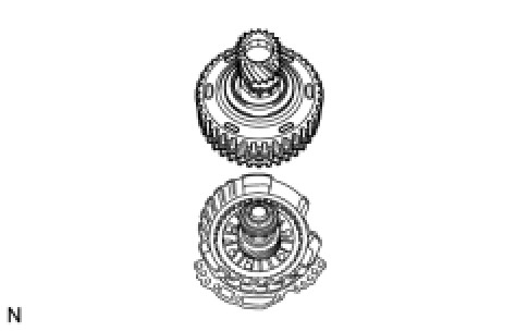
26. REMOVE NO. 3 BRAKE HUB
(a) Remove the No. 3 brake hub from the underdrive planetary gear assembly.
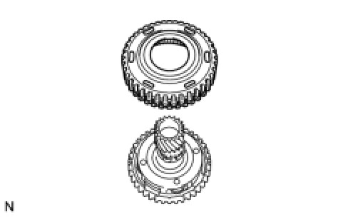
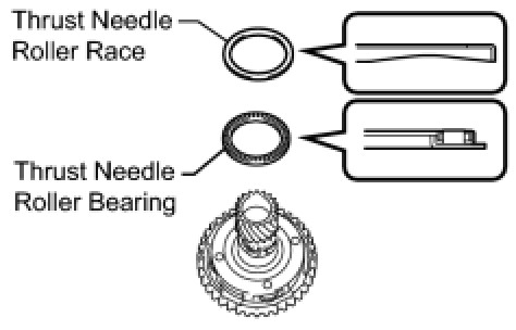
(b) Remove the thrust needle roller bearing and thrust needle roller race from the underdrive planetary gear assembly.
27. REMOVE PLANETARY SUN GEAR SUB-ASSEMBLY
(a) While expanding the snap ring with snap ring pliers, remove the planetary sun gear from the underdrive planetary gear assembly.
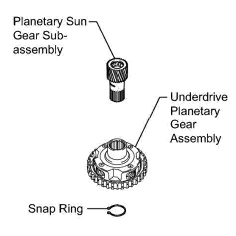
(b) Remove the snap ring from the underdrive planetary gear assembly.
28. INSPECT UNDERDRIVE PLANETARY GEAR ASSEMBLY Transaxle Unit
29. INSPECT PLANETARY SUN GEAR SUB-ASSEMBLY Transaxle Unit
30. REMOVE INPUT SHAFT SUB-ASSEMBLY
(a) Remove the input shaft sub-assembly from the oil pump assembly.
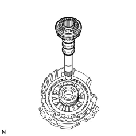
(b) Remove the thrust needle roller bearing and thrust needle roller race from the input shaft.
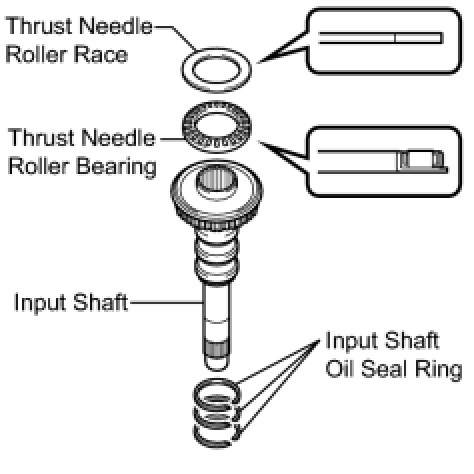
(c) Using a screwdriver, remove the 3 input shaft oil seal rings from the input shaft.
31. REMOVE UNDERDRIVE PLANETARY SUN GEAR
(a) Remove the underdrive planetary sun gear from the oil pump assembly.
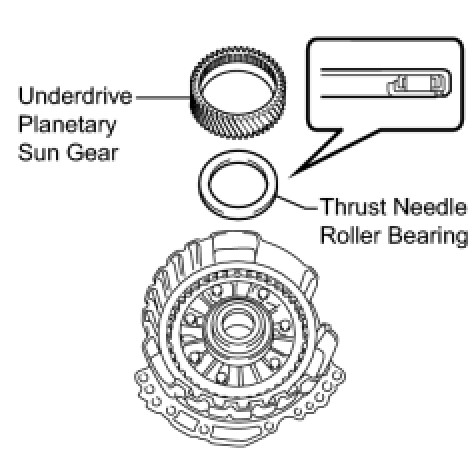
(b) Remove the thrust needle roller bearing from the oil pump assembly.
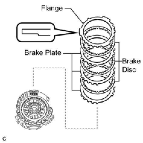
32. REMOVE NO. 1 BRAKE DISC
(a) Using a screwdriver, remove the 2 snap rings and brake snap ring stopper from the oil pump assembly.
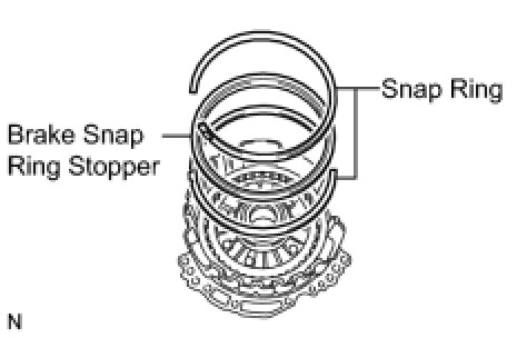
(b) Remove the flange, 3 brake discs, and 3 brake plates from the oil pump assembly.
33. INSPECT NO. 1 BRAKE DISC Transaxle Unit
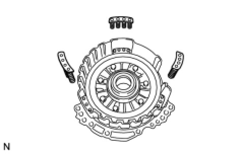
34. REMOVE 2ND BRAKE PISTON RETURN SPRING SUB-ASSEMBLY
(a) Remove the 3 2nd brake piston return springs from the oil pump assembly.
35. INSPECT 2ND BRAKE PISTON RETURN SPRING SUB-ASSEMBLY Transaxle Unit
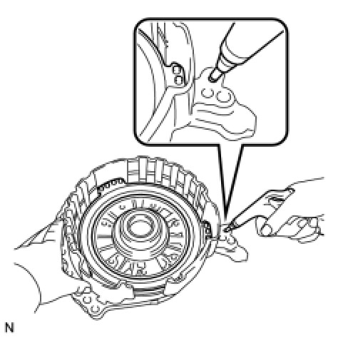
36. REMOVE NO. 1 BRAKE PISTON
(a) Holding the oil pump assembly by hand, apply compressed air (392 kPa, 4.0 kgf/cm2, 57 psi) to the oil pump assembly to remove the No. 1 brake piston.
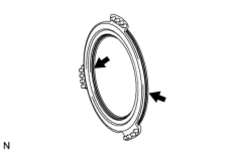
(b) Using a screwdriver, remove the 2 O-rings from the No. 1 brake piston.
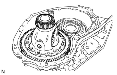
37. REMOVE FRONT DIFFERENTIAL CASE
(a) Remove the front differential case from the transaxle case.
38. REMOVE COUNTER DRIVE GEAR NUT
(a) Using SST and a hammer, unstake the counter drive gear nut.
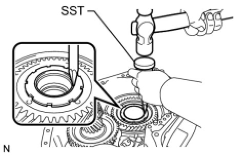
SST : 09930-00010
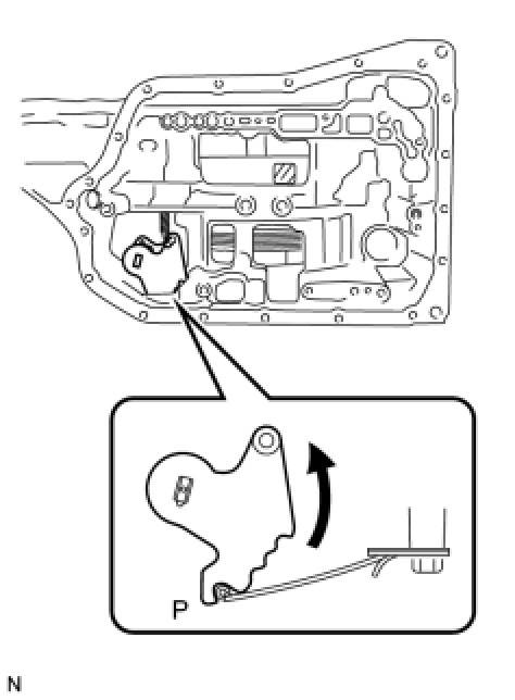
(b) Turn the manual valve lever shaft counterclockwise to set it to the P position as shown in the illustration.
(c) Using SST, remove the counter drive gear nut from the planetary gear assembly.
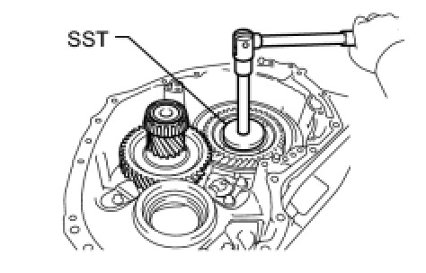
SST : 09387-00130
39. REMOVE COUNTER DRIVEN GEAR
(a) Turn the manual valve lever shaft 2 notches clockwise to set it to the N position as shown in the illustration.
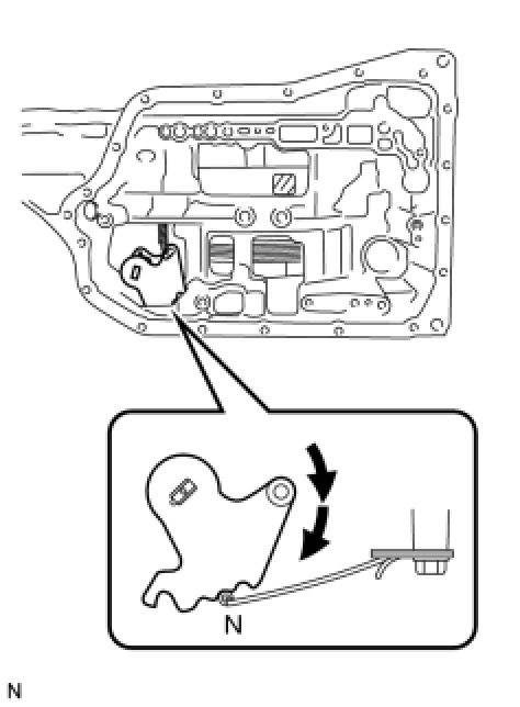
(b) Remove the counter driven gear from the transaxle case.