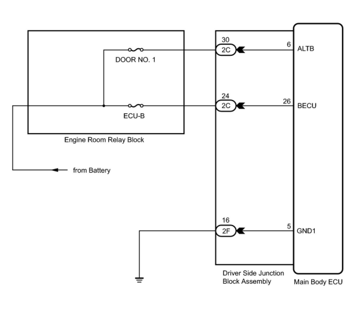
ECU Power Source Circuit
THEFT DETERRENT / KEYLESS ENTRY: THEFT DETERRENT SYSTEM (w/ Smart Key System): ECU Power Source Circuit
- ECU Power Source Circuit
DESCRIPTION
This circuit provides power for main body ECU (driver side junction block assembly) operation.
WIRING DIAGRAM
INSPECTION PROCEDURE
PROCEDURE
1. CHECK DRIVER SIDE JUNCTION BLOCK ASSEMBLY (MAIN BODY ECU (POWER SOURCE))
(a) Disconnect the 2C driver side junction block assembly connector.
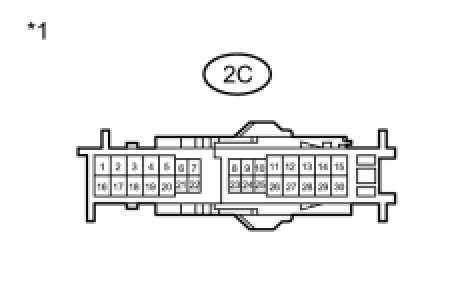
(b) Measure the voltage according to the value(s) in the table below.
Standard Voltage:
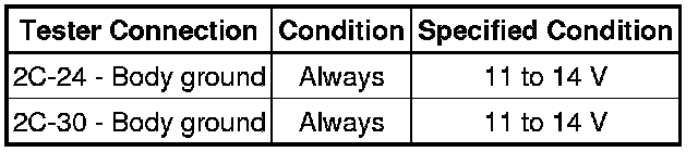
Text in Illustration

NG -- REPAIR OR REPLACE HARNESS OR CONNECTOR
OK -- Continue to next step.
2. CHECK HARNESS AND CONNECTOR (DRIVER SIDE JUNCTION BLOCK ASSEMBLY - BODY GROUND)
(a) Disconnect the 2F driver side junction block assembly connectors.
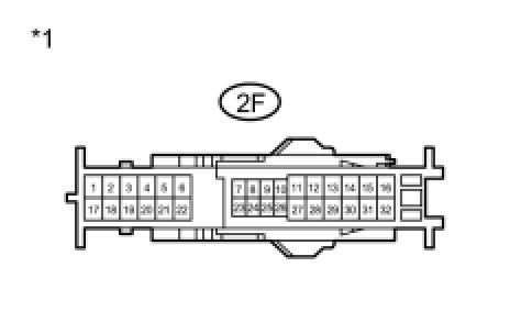
(b) Measure the resistance according to the value(s) in the table below.
Standard Resistance:
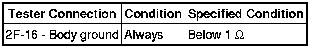
Text in Illustration
NG -- REPAIR OR REPLACE HARNESS OR CONNECTOR
OK -- PROCEED TO NEXT SUSPECTED AREA SHOWN IN PROBLEM SYMPTOMS TABLE Theft Deterrent System (w/ Smart Key System)