Reassembly
1GR-FE BATTERY / CHARGING: GENERATOR: REASSEMBLY
1. INSTALL GENERATOR DRIVE END FRAME BEARING
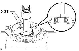
(a) Using SST and a press, press in a new generator drive end frame bearing.
SST : 09950-60010
09951-00470
SST : 09950-70010
09951-07100
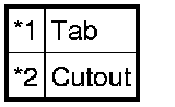
(b) Fit the tabs on the retainer plate into the cutouts on the drive end frame to install the retainer plate.
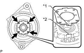
Text in Illustration
(c) Install the 4 screws.
Torque : 2.3 Nm (23 kgf-cm, 20 in-lbf)
2. INSTALL GENERATOR ROTOR ASSEMBLY
(a) Install the generator rotor assembly to the drive end frame.
(b) Place the generator washer on the generator rotor.
3. INSTALL GENERATOR COIL ASSEMBLY
(a) Using a deep socket wrench (21 mm) and press, slowly press in the generator coil assembly.
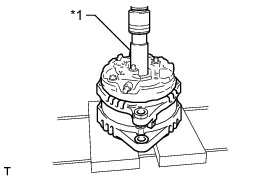
Text in Illustration

(b) Install the 4 bolts.
Torque : 5.9 Nm (60 kgf-cm, 52 in-lbf)
4. INSTALL GENERATOR BRUSH HOLDER ASSEMBLY
(a) While pushing the 2 brushes into the generator brush holder, insert a pin with a diameter of 1.0 mm (0.0394 in.) into the brush holder hole.

Text in Illustration

(b) Install the generator brush holder to the generator coil with the 2 screws.
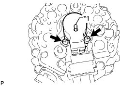
Torque : 1.8 Nm (18 kgf-cm, 16 in-lbf)
Text in Illustration

(c) Pull out the pin from the generator brush holder.
5. INSTALL TERMINAL INSULATOR
(a) Install the terminal insulator to the generator coil.
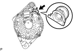
NOTICE:
Make sure the terminal insulator is installed facing the proper direction.
6. INSTALL GENERATOR REAR END COVER
(a) Install the generator rear end cover to the generator coil with the 3 nuts.
Torque : 4.6 Nm (46 kgf-cm, 40 in-lbf)
(b) Install the cord clip with the nut.
Torque : 6.2 Nm (63 kgf-cm, 55 in-lbf)
7. INSTALL GENERATOR WITH CLUTCH PULLEY
(a) Temporarily install the generator with clutch pulley by hand.
(b) Mount the generator in a vise between aluminum plates.
(c) Install SST (A) and SST (B) to the generator with clutch pulley as shown in the illustration.
SST : 09820-63021
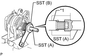
Text in Illustration

NOTICE:
Securely attach SST to the generator with clutch pulley and generator rotor shaft.
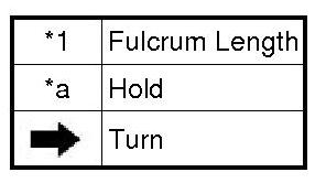
(d) Using a wrench to hold SST (A), turn SST (B) clockwise to tighten the generator with clutch pulley.
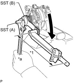
without SST - Torque : 80 Nm (816 kgf-cm, 59 ft-lbf)
with SST - Torque : 64 Nm (653 kgf-cm, 47 ft-lbf)
Text in Illustration
HINT
* Use a torque wrench with a fulcrum length of 400 mm (15.7 in.). When using a torque wrench with a fulcrum length that is not 400 mm (15.7 in.), calculate the torque specification for the torque wrench and SST based on the "without SST" torque specification Service Precautions.
* Make sure SST and the wrench are connected in a straight line.
NOTICE:
Be careful as the generator with clutch pulley or generator rotor shaft may be damaged if the position of SST is not securely maintained while performing this operation.
(e) Remove SST from the generator.
(f) Check that the generator with clutch pulley rotates smoothly.
8. INSTALL GENERATOR PULLEY CAP
(a) Install a new generator pulley cap to the clutch pulley.