System Diagram
NETWORKING: CAN COMMUNICATION SYSTEM: SYSTEM DIAGRAM
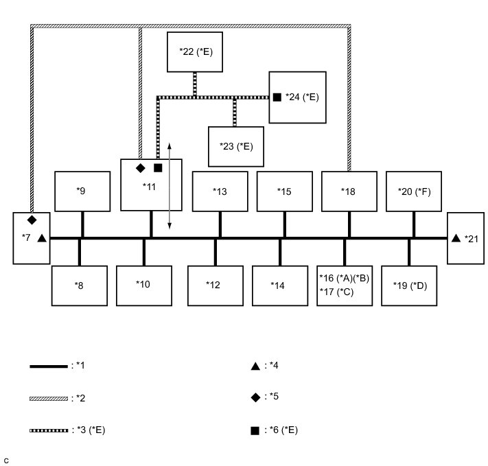
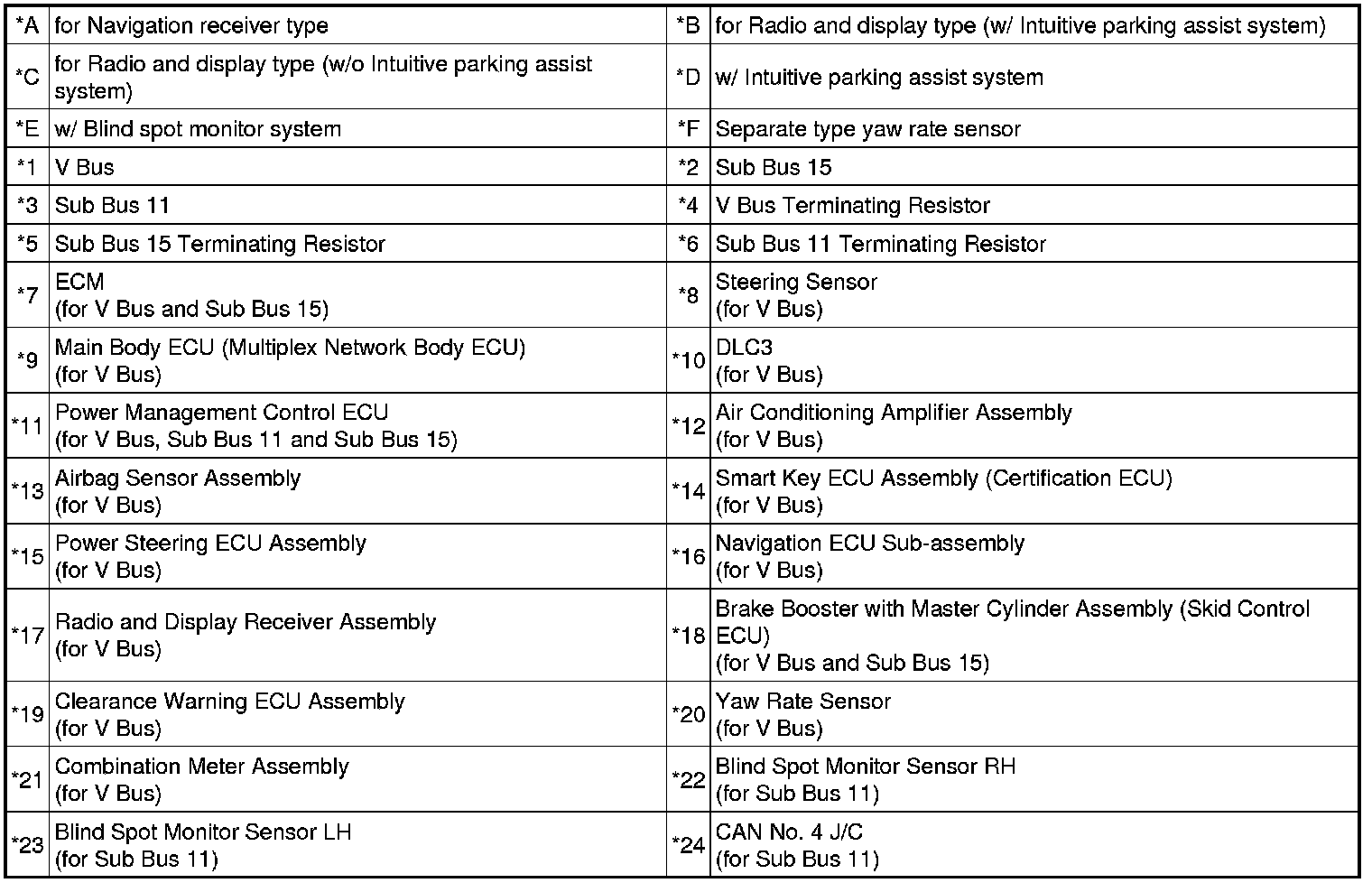
1. OVERALL CAN BUS DIAGRAM
(a) Control system CAN is composed of 3 buses.
Text in Illustration
HINT
* The power management control ECU functions as a gateway between the V bus and sub bus 11.
* Refer to the following bus wiring diagrams for details.
2. V BUS
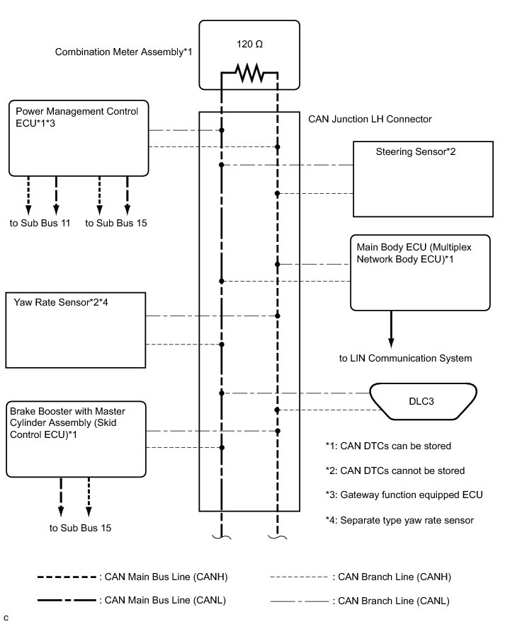
HINT
The CAN communication system connects to other network via ECUs that function as a gateway System Diagram.
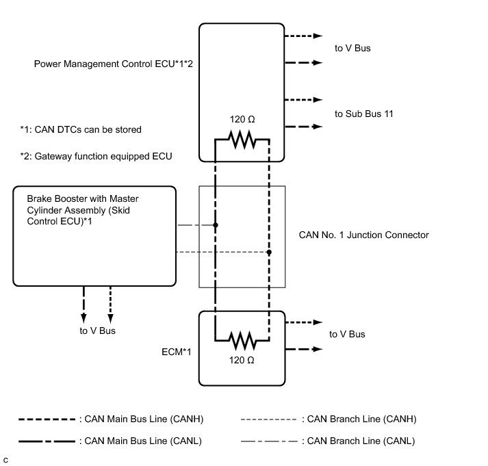
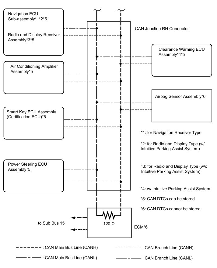
3. SUB BUS 11 (w/ BLIND SPOT MONITOR SYSTEM)
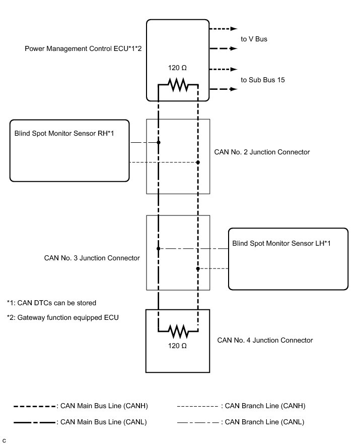
4. SUB BUS 15