Cylinder Head Assembly
CYLINDER HEAD SUB-ASSEMBLYINSPECT CYLINDER HEAD BOLT
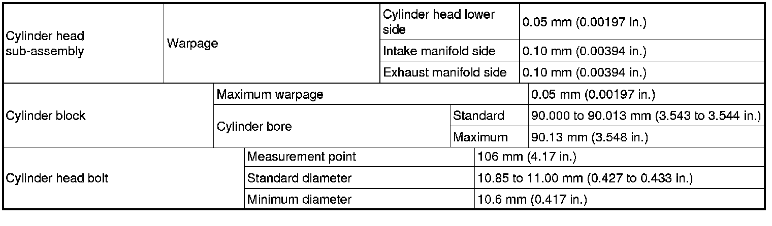
(a) Using a vernier caliper, measure the diameter of the threads at the measurement point.

Text in Illustration

Standard diameter:
10.85 to 11.00 mm (0.427 to 0.433 in.)
Minimum diameter:
10.6 mm (0.417 in.)
Measurement point (distance from the seat):
106 mm (4.17 in.)
HINT
* If the diameter is less than the minimum, replace the cylinder head bolt. Failure to do so may lead to engine damage.
* If there is any thread deformation, replace the cylinder head bolt with a new one.
The cylinder head bolts are tightened in 4 progressive steps.
Step 1
Using a 10 mm bi-hexagon wrench, install and uniformly tighten the 10 cylinder head bolts in several steps, in the sequence shown in the illustration.

Torque 36 Nm (367 kgf-cm, 27 ft-lbf)
Step 2
Tighten the cylinder head bolts again in the sequence shown in the illustration to make sure that they are tightened to the specified torque.
Torque 36 Nm (367 kgf-cm, 27 ft-lbf)
Step 3
Mark each cylinder head bolt head with paint as shown in the illustration.

Text in Illustration
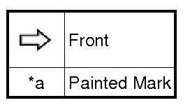
Tighten the cylinder head bolts 90° in the sequence shown in step 1.
Step 4
Tighten the cylinder head bolts another 90° in the sequence shown in step 1.
SURFACE VARIATION
CAMSHAFT BEARING CAP
Confirm the marks and numbers on the camshaft bearing caps and place them in their proper positions and directions.
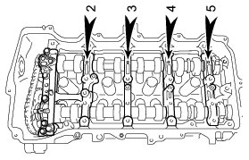
Using several steps, uniformly tighten the 10 bolts in the sequence shown in the illustration.
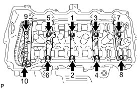
Torque 27 Nm (275 kgf-cm, 20 ft-lbf)
Using several steps, uniformly tighten the 11 bolts in the sequence shown in the illustration.
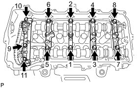
Torque 16 Nm (163 kgf-cm, 12 ft-lbf)
CAMSHAFT HOUSING SUB-ASSEMBLY
Install the camshaft housing, and then install the 20 bolts in the order shown in the illustration.
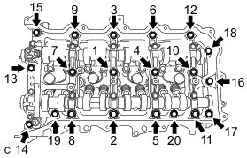
Torque 27 Nm (275 kgf-cm, 20 ft-lbf)
INTAKE MANIFOLD TORQUE & SEQUENCE Specifications
EXHAUST MANIFOLD TORQUE & SEQUENCE Specifications
CAMSHAFT GEAR/SPROCKET TORQUE Specifications