Part 3
2GR-FXE ENGINE CONTROL SYSTEM: SFI SYSTEM: EVAP System - (Continued)
- EVAP System
48. CHECK HARNESS AND CONNECTOR (PURGE VSV - ECM)
(a) Disconnect the ECM connector and the purge VSV connector.
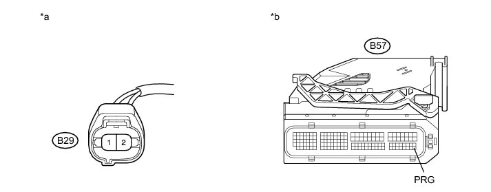
(b) Measure the resistance according to the value(s) in the table below.
Standard Resistance:

Text in Illustration

(c) Reconnect the connectors.
NG -- REPAIR OR REPLACE HARNESS OR CONNECTOR
OK -- Continue to next step.
49. REPLACE ECM
(a) Replace the ECM Removal.
NEXT -- PERFORM EVAPORATIVE SYSTEM CHECK AGAIN (AUTOMATIC MODE)
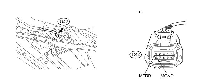
50. CHECK CANISTER PUMP MODULE (VACUUM PUMP POWER SOURCE CIRCUIT)
(a) Turn the ignition switch off.
(b) Remove the canister lower cover.
(c) Disconnect the canister pump module connector.
(d) Connect the Techstream to the DLC3.
(e) Turn the ignition switch to ON.
(f) Enter the following menus: Powertrain / Engine and ECT / Active Test / Activate the Vacuum Pump.
(g) Turn the vacuum pump on using the Techstream.
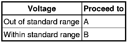
(h) Measure the voltage according to the value(s) in the table below.
Text in Illustration

Standard Voltage:

Result:
(i) Reconnect the connector.
(j) Reinstall the canister lower cover.
B -- CHECK CANISTER PUMP MODULE (VENT VALVE POWER SOURCE CIRCUIT)
A -- Continue to next step.
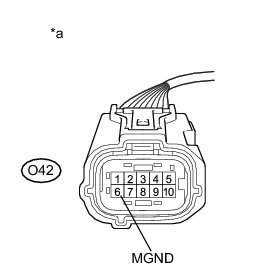
51. CHECK HARNESS AND CONNECTOR (VACUUM PUMP - BODY GROUND)
(a) Disconnect the canister pump module connector.
(b) Turn the ignition switch off.
(c) Measure the resistance according to the value(s) in the table below.
Standard Resistance:

Text in Illustration

(d) Reconnect the connector.
NG -- REPAIR OR REPLACE HARNESS OR CONNECTOR
OK -- Continue to next step.
52. CHECK HARNESS AND CONNECTOR (VACUUM PUMP - ECM)
(a) Disconnect the ECM connector.
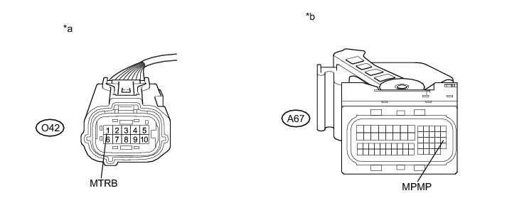
(b) Measure the resistance according to the value(s) in the table below.
Standard Resistance:

Text in Illustration

(c) Connect the ECM connector.
NG -- REPAIR OR REPLACE HARNESS OR CONNECTOR
OK -- Continue to next step.
53. REPLACE ECM
(a) Replace the ECM Removal.
NEXT -- PERFORM EVAPORATIVE SYSTEM CHECK AGAIN (AUTOMATIC MODE)
54. CHECK CANISTER PUMP MODULE (VENT VALVE POWER SOURCE CIRCUIT)
(a) Turn the ignition switch off.
(b) Remove the canister lower cover.
(c) Disconnect the canister pump module connector.
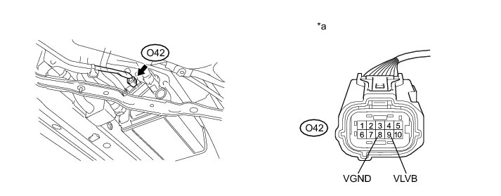
(d) Connect the Techstream to the DLC3.
(e) Turn the ignition switch to ON.
(f) Enter the following menus: Powertrain / Engine and ECT / Active Test / Activate the Vacuum Pump.
(g) Turn the vacuum pump on using the Techstream.
(h) Measure the voltage according to the value(s) in the table below.
Text in Illustration

Standard Voltage:

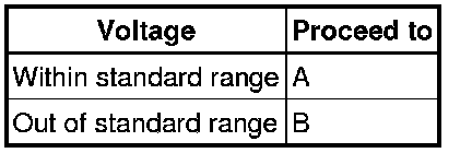
Result:
(i) Reconnect the connector.
(j) Reinstall the canister lower cover.
B -- CHECK HARNESS AND CONNECTOR (VENT VALVE - ECM)
A -- Continue to next step.
55. CHECK HARNESS AND CONNECTOR (VENT VALVE - BODY GROUND)
(a) Turn the ignition switch off.
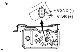
(b) Remove the canister lower cover.
(c) Disconnect the canister pump module connector.
(d) Apply battery voltage to VLVB and VGND terminals of the canister pump module.
(e) Touch the canister pump module to confirm the vent valve operation.
Text in Illustration

Result:

(f) Reconnect the connector.
(g) Reinstall the canister lower cover.
B -- REPLACE CANISTER
A -- Continue to next step.
56. CHECK HARNESS AND CONNECTOR (VENT VALVE - ECM)
(a) Disconnect the ECM connector.
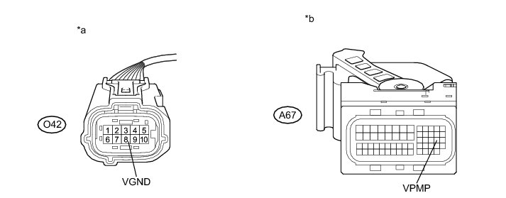
(b) Measure the resistance according to the value(s) in the table below.
Standard Resistance:

Text in Illustration

(c) Connect the ECM connector.
NG -- REPAIR OR REPLACE HARNESS OR CONNECTOR
OK -- Continue to next step.
57. REPLACE ECM
(a) Replace the ECM Removal.
NEXT -- PERFORM EVAPORATIVE SYSTEM CHECK AGAIN (AUTOMATIC MODE)
58. CHECK HOSES (PURGE VSV - CANISTER)
(a) Remove the canister lower cover.
(b) Connect the pressure gauge to the canister pump module with the adapter.
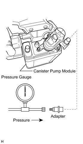
(c) Connect the Techstream to the DLC3.
(d) Turn the ignition switch to ON.
(e) Pressurize the EVAP system to between 3.2 and 3.7 kPa-g (24 and 28 mmHg-g).
NOTICE:
More than 4.7 kPa-g (35 mmHg-g) of pressure will damage the EVAP system. Pay attention to the pressure.
(f) Apply soapy water to the piping and connections of the EVAP system. Look for the area where bubbles appear.
HINT
* If the system has leaks, a whistling sound will be heard.
* Disconnect the hose between the canister and fuel tank from the canister. Close the canister on the area where the hose was connected and perform an inspection. The fuel tank can be eliminated from the suspected areas for leak checks.
(g) Reinstall the canister lower cover.
NEXT -- Continue to next step.
59. REPLACE MALFUNCTIONING PARTS, COMPONENT AND AREA
NEXT -- PERFORM EVAPORATIVE SYSTEM CHECK AGAIN (AUTOMATIC MODE)
60. CHECK FUEL VAPOR-CONTAINMENT VALVE ASSEMBLY (POWER SOURCE CIRCUIT)
(a) Turn the ignition switch off.
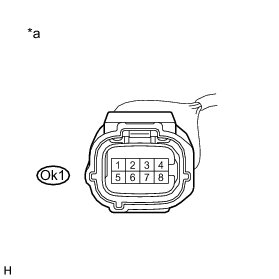
(b) Disconnect the Ok1 connector.
(c) Connect the Techstream to the DLC3.
(d) Turn the ignition switch to ON.
(e) Enter the following menus: Powertrain / Engine and ECT / Active Test / Activate the Fuel Vapor-Containment Valve.
(f) Turn the fuel vapor-containment valve ON using the Techstream.
(g) Measure the voltage according to the value(s) in the table below.
Standard Voltage:

Result:
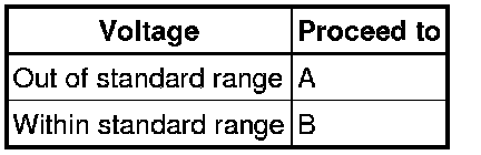
Text in Illustration

(h) Reconnect the connector.
B -- CHECK HARNESS AND CONNECTOR (TANK WIRE HARNESS)
A -- Continue to next step.
61. CHECK HARNESS AND CONNECTOR (FUEL VAPOR-CONTAINMENT VALVE POWER SOURCE)
(a) Disconnect the Ok1 connector.
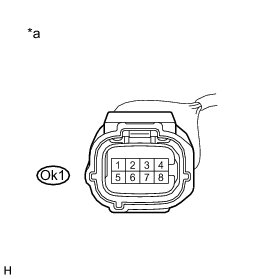
(b) Turn the ignition switch to ON.
(c) Measure the voltage according to the value(s) in the table below.
Standard Voltage:

Text in Illustration

(d) Reconnect the connector.
NG -- REPAIR OR REPLACE HARNESS OR CONNECTOR
OK -- Continue to next step.
62. CHECK HARNESS AND CONNECTOR (TANK WIRE HARNESS)
(a) Remove the fuel tank assembly Removal.
(b) Disconnect the Ok1 connector.
(c) Disconnect the fuel vapor-containment valve connector.
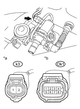
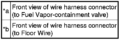
(d) Measure the resistance according to the value(s) in the table below.
Standard Resistance:
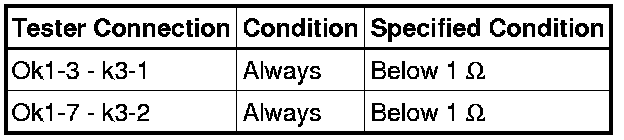
(e) Reinstall the fuel tank assembly Installation.
Text in Illustration
(f) Reconnect the connectors.
(g) Reinstall the fuel tank assembly.
NG -- REPAIR OR REPLACE HARNESS OR CONNECTOR
OK -- Continue to next step.
63. REPLACE ECM
(a) Replace the ECM Removal.
NEXT -- PERFORM EVAPORATIVE SYSTEM CHECK AGAIN (AUTOMATIC MODE)
64. REPLACE PURGE VSV
(a) Replace the purge VSV Removal.
NOTICE:
* When replacing the canister, check the canister pump module interior and related pipes for water, fuel and other liquids. If liquids are present, check for disconnections and/or cracks in the following: 1) the pipe from the air inlet port to the canister pump module; 2) the canister filter; and 3) the fuel tank vent hose.
* Check for filter blockage in the canister filter. If the canister filter has blockages, replace the canister filter.
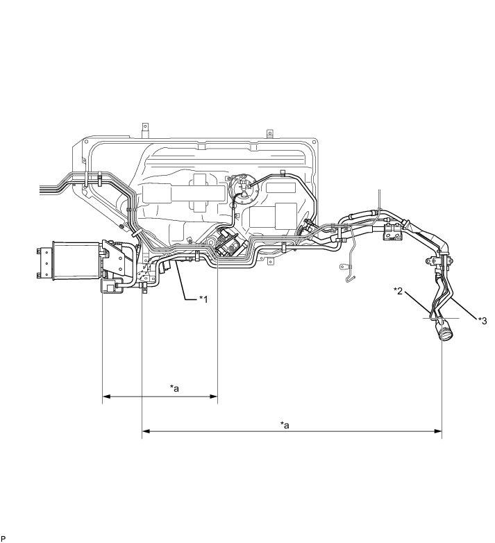
Text in Illustration

NEXT -- PERFORM EVAPORATIVE SYSTEM CHECK AGAIN (AUTOMATIC MODE)
65. REPLACE CANISTER
(a) Replace the canister Removal.
NEXT -- PERFORM EVAPORATIVE SYSTEM CHECK AGAIN (AUTOMATIC MODE)
66. CHECK HARNESS AND CONNECTOR (TANK WIRE HARNESS)
(a) Remove the fuel tank assembly Removal.
(b) Disconnect the Ok1 connector.
(c) Disconnect the fuel vapor-containment valve connector.
(d) Measure the resistance according to the value(s) in the table below.
Standard Resistance:
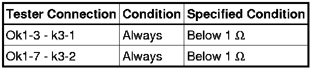
(e) Reinstall the fuel tank assembly Installation.
Text in Illustration
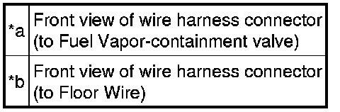
(f) Reconnect the connectors.
(g) Reinstall the fuel tank assembly.
NG -- REPAIR OR REPLACE HARNESS OR CONNECTOR
OK -- Continue to next step.
67. REPLACE FUEL VAPOR-CONTAINMENT VALVE
(a) Replace the fuel vapor-containment valve Removal.
NEXT -- PERFORM EVAPORATIVE SYSTEM CHECK AGAIN (AUTOMATIC MODE)
68. REPAIR OR REPLACE HARNESS OR CONNECTOR
NEXT -- PERFORM EVAPORATIVE SYSTEM CHECK AGAIN (AUTOMATIC MODE)
69. REPAIR OR REPLACE VACUUM HOSE (PURGE VSV - THROTTLE WITH MOTOR BODY ASSEMBLY)
NEXT -- PERFORM EVAPORATIVE SYSTEM CHECK AGAIN (AUTOMATIC MODE)