Part 2
INTRODUCTION: REPAIR INSTRUCTION: PRECAUTION - (Continued)
(b) SPIRAL CABLE

(1) The steering wheel must be fitted correctly to the steering column with the spiral cable at the neutral position, as otherwise cable disconnection and other problems may occur. Refer to the information about correct installation of the steering wheel Installation.
(c) STEERING PAD
(1) Always place a removed or new steering pad surface upward as shown in the illustration. Placing the steering pad of the pad surface facing down could cause a serious accident if the airbag deploys. Also, do not place anything on top of the steering pad.

(2) Never measure the resistance of the airbag squib. This may cause the airbag to deploy, which could cause serious injury.

(3) Grease or detergents of any kind should not be applied to the steering pad.
(4) Store the steering pad in an area where the ambient temperature is below 93°C (200°F), the humidity is not high and there is no electrical noise.
(5) Before using an electric welder anywhere on the vehicle, disconnect the center airbag sensor assembly connectors. These connectors contain shorting springs. This feature reduces the possibility of the airbag deploying due to current entering the squib wiring.
(6) When disposing of the vehicle or the steering pad by itself, the airbag should be deployed using SST before disposal Steering Pad. Deploy the airbag in a safe place away from electrical noise.
(d) FRONT PASSENGER AIRBAG ASSEMBLY
(1) Always place a removed or new front passenger airbag assembly with the pad surface facing upward as shown in the illustration. Placing the airbag assembly with the airbag deployment direction facing down could cause a serious accident if the airbag deploys.

(2) Never measure the resistance of the airbag squib. This may cause the airbag to deploy, which could cause serious injury.

(3) Grease or detergents of any kind should not be applied to the front passenger airbag assembly.
(4) Store the airbag assembly in an area where the ambient temperature is below 93°C (200°F), the humidity is not high and there is no electrical noise.
(5) Before using an electric welder anywhere on the vehicle, disconnect the center airbag sensor assembly connectors. These connectors contain shorting springs. This feature reduces the possibility of the airbag deploying due to current entering the squib wiring.
(6) When disposing of the vehicle or the airbag assembly unit by itself, the airbag should be deployed using SST before disposal Front Passenger Airbag Assembly. Deploy the airbag in a safe place away from electrical noise.
(e) DRIVER SIDE KNEE AIRBAG ASSEMBLY
(1) Always place a removed or new driver side knee airbag assembly with the airbag deployment direction facing upward. Placing the airbag assembly with the airbag deployment direction facing downward could cause a serious accident if the airbag deploys.

(2) Never measure the resistance of the airbag squib. This may cause the airbag to deploy, which could cause serious injury.

(3) Grease or detergents of any kind should not be applied to the driver side knee airbag assembly.
(4) Store the driver side knee airbag assembly where the ambient temperature is below 93°C (200°F), the humidity is not high and there is no electrical noise.
(5) Before using an electric welder anywhere on the vehicle, disconnect the center airbag sensor assembly connectors. These connectors contain shorting springs. This feature reduces the possibility of the airbag deploying due to current entering the squib wiring.
(6) When disposing of a vehicle or driver side knee airbag assembly unit by itself, the airbag should be deployed using SST before disposal Driver Side Knee Airbag Assembly. Deploy in a safe place, away from electrical noise.
(f) FRONT SEAT SIDE AIRBAG ASSEMBLY
(1) Always place a removed or new front seat side airbag assembly with the airbag deployment direction facing up.
(2) Never measure the resistance of the airbag squib. This may cause the airbag to deploy, which could cause serious injury.

(3) Grease or detergents of any kind should not be applied to the front seat side airbag assembly.
(4) Store the airbag assembly in an area where the ambient temperature is below 93°C (200°F), the humidity is not high and there is no electrical noise.
(5) Before using an electric welder anywhere on the vehicle, disconnect the center airbag sensor assembly connectors. These connectors contain shorting springs. This feature reduces the possibility of the airbag deploying due to current entering the squib wiring.
(6) When disposing of a vehicle or the airbag assembly unit by itself, the airbag should be deployed using SST before disposal Front Seat Side Airbag Assembly (for Power Seat). Deploy the airbag in a safe place away from electrical noise.
(g) CURTAIN SHIELD AIRBAG ASSEMBLY
(1) Always place a removed or new curtain shield airbag assembly in a clear plastic bag, and keep it in a safe place.

CAUTION:
The plastic bag should be disposed of after use.
NOTICE:
Never disassemble the curtain shield airbag assembly.
(2) Never measure the resistance of the airbag squib. This may cause the airbag to deploy, which could cause serious injury.

(3) Grease or detergents of any kind should not be applied to the curtain shield airbag assembly.
(4) Store the airbag assembly in an area where the ambient temperature is below 93°C (200°F), the humidity is not high and there is no electrical noise.
(5) Before using an electric welder anywhere on the vehicle, disconnect the center airbag sensor assembly connectors. These connectors contain shorting springs. This feature reduces the possibility of the airbag deploying due to current entering the squib wiring.
(6) When disposing of a vehicle or the airbag assembly unit by itself, the airbag should be deployed using SST before disposal Curtain Shield Airbag Assembly. Deploy the airbag in a safe place away from electrical noise.
(h) FRONT SEAT OUTER BELT ASSEMBLY (SEAT BELT PRETENSIONER)
(1) Never measure the resistance of the front seat outer belt assembly. This may cause the pretensioner of the front seat outer belt assembly to activate, which could cause serious injury.

(2) Never disassemble the front seat outer belt assembly.
(3) Never install the front seat outer belt assembly on another vehicle.
(4) Store the front seat outer belt assembly in an area where the ambient temperature is below 80°C (176°F), the humidity is not high and there is no electrical noise.
(5) Before using an electric welder anywhere on the vehicle, disconnect the center airbag sensor assembly connectors. These connectors contain shorting springs. This feature reduces the possibility of the airbag deploying due to current entering the squib wiring.
(6) When disposing of a vehicle or the front seat outer belt assembly unit by itself, the front seat outer belt assembly should be activated before disposal Procedures. Activate the front seat outer belt assembly in a safe place away from electrical noise.
(7) As the front seat outer belt assembly is hot after being activated, allow some time for it to cool down sufficiently before disposal. Never apply water to cool down the front seat outer belt assembly.
(8) Grease, detergents, oil or water should not be applied to the front seat outer belt assembly.
(i) CENTER AIRBAG SENSOR ASSEMBLY
(1) Never reuse a center airbag sensor assembly that has been involved in a collision where the SRS has deployed.
(2) The connectors to the center airbag sensor assembly should be connected or disconnected with the sensor installed to the vehicle. If the connectors are connected or disconnected while the center airbag sensor assembly is not placed installed, the SRS may activate.
(3) Work must be started at least 90 seconds after the ignition switch is turned off and the cable is disconnected from the negative (-) battery terminal, even if only loosening the bolts of the center airbag sensor assembly.
(j) WIRE HARNESS AND CONNECTOR
(1) All the connectors in the system are a standard yellow color. If the SRS wire harness has an open circuit or the connector becomes broken, replace it.
8. ELECTRONIC CONTROL

(a) REMOVAL AND INSTALLATION OF BATTERY TERMINAL
NOTICE:
Certain systems need to be initialized after reconnecting the cable to the negative (-) battery terminal.
(1) Before performing electrical work, disconnect the cable from the negative (-) battery terminal to prevent component and wire damage caused by accidental short circuits.
(2) When disconnecting the cable, turn the ignition switch and headlight switch off and loosen the cable nut completely. Perform these operations without twisting or prying the cable. Then disconnect the cable.
(3) Clock settings, radio settings, audio system memory, DTCs and other data are erased when the cable is disconnected from the negative (-) battery terminal. Write down any necessary data before disconnecting the cable.
(b) HANDLING OF ELECTRONIC PARTS

(1) Do not open the cover or case of the ECU unless absolutely necessary. If the IC terminals are touched, the IC may be rendered inoperative by static electricity.
(2) Do not pull the wires when disconnecting electronic connectors. Pull the connector itself.
(3) Do not drop electronic components, such as sensors or relays. If they are dropped on a hard surface, they should be replaced.
(4) When cleaning the engine with steam, protect the electronic components, air filter and emission-related components from water.
(5) Never use an impact wrench to remove or install temperature switches or temperature sensors.
(6) When measuring the resistance between terminals of a wire connector, insert the tester probe carefully to prevent terminals from bending.
9. REMOVAL AND INSTALLATION OF FUEL CONTROL PARTS
(a) PLACE FOR REMOVING AND INSTALLING FUEL SYSTEM PARTS
(1) Work in a location with good air ventilation that does not have welders, grinders, drills, electric motors, stoves, or any other ignition sources.
(2) Never work in a pit or near a pit as vaporized fuel will collect in those places.
(b) REMOVING AND INSTALLING FUEL SYSTEM PARTS
(1) Prepare a fire extinguisher before starting the operation.
(2) To prevent static electricity, install a ground wire to the fuel changer, vehicle and fuel tank, and do not spray the surrounding area with water. Be careful when performing work in this area, as the work surface will become slippery. Do not clean up gasoline spills with water, as this may cause the gasoline to spread, and possibly create a fire hazard.
(3) Avoid using electric motors, working lights and other electric equipment that can cause sparks or high temperatures.
(4) Avoid using iron hammers as they may create sparks.
(5) Dispose of fuel-contaminated cloth separately using a fire resistant container.
10. REMOVAL AND INSTALLATION OF ENGINE INTAKE PARTS
(a) If any metal particles enter intake system parts, this may damage the engine.
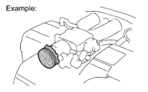
(b) When removing and installing intake system parts, cover the openings of the removed parts and engine openings. Use adhesive tape or other suitable materials.
(c) When installing intake system parts, check that no metal particles have entered the engine or installed parts.
11. HANDLING OF HOSE CLAMPS

(a) Before removing a hose, check the clamp position so that it can be reinstalled in the same position.
(b) Replace any deformed or dented clamps with new ones.
(c) When reusing a hose, attach the clamp on the clamp track portion of the hose.
(d) For a spring type clamp, you may want to spread the tabs slightly after installation by pushing in the direction of the arrows as shown in the illustration.
12. FOR VEHICLES EQUIPPED WITH MOBILE COMMUNICATION SYSTEMS

(a) Install the antenna far away from the ECU and sensors of the vehicle electronic systems as possible.
(b) Install an antenna feeder at least 20 cm (7.87 in.) away from the ECU and sensors of the vehicle electronic systems. For details about ECU and sensor locations, refer to the section on the applicable components.
(c) Keep the antenna and feeder separate from other wiring as much as possible. This will prevent signals sent from the communication equipment from affecting vehicle equipment and vice-versa.
(d) Check that the antenna and feeder are correctly adjusted.
(e) Do not install a high-powered mobile communication system.
13. FOR VEHICLES EQUIPPED WITH TRACTION CONTROL (TRAC) AND VEHICLE STABILITY CONTROL (VSC) SYSTEMS
(a) NOTICES FOR WHEN TESTING WITH DRUM TESTER
(1) When testing with a 2-wheel drum tester such as a speedometer tester, a combination speedometer and brake tester, or a chassis dynamometer, perform the following procedure to enter inspection mode and disable the TRAC and VSC systems Component Tests and General Diagnostics.
NOTICE:
* If the vehicle is tested in normal mode on the tester, TRAC and VSC operation may cause the vehicle to jump out from the tester.
* Check that "2WD Maintenance Mode" is displayed on the multi-information display.
* Secure the vehicle with chains for safety.
HINT
Pressing the VSC OFF switch (for vehicles with a VSC OFF switch) does not disable TRAC and VSC operation completely.
(b) NOTICES FOR VSC RELATED PROCEDURES
(1) For VSC related parts, adjustments are required after removal and installation. Therefore, perform removal and installation only when necessary.
(2) When performing VSC related procedures, be sure to strictly follow the preparation and completion procedures.
(3) When performing removal and installation or replacement of VSC related parts, first disconnect the cable from the negative (-) battery terminal.
14. WHEN INSPECTING VEHICLES
NOTICE:
If the vehicle is run in the inspection mode, for such as a speedometer test, a DTC may be set. Therefore, if the warning light comes on, after canceling the inspection mode, check for DTCs using the Techstream and clear the DTCs.
(a) VEHICLE CONDITIONS
(1) Before activating inspection mode, turn the air conditioning off, start the engine with the shift lever in P, and check the engine stops within several seconds after starting (engine warm up check).
(2) Activate inspection mode and inspect the vehicle Component Tests and General Diagnostics.
The shift position for each test is as follows:

(3) Reset inspection mode immediately after completion of inspection.
NOTICE:
Driving the vehicle without resetting inspection mode may damage the transaxle.
(b) WHEN USING A BRAKE TESTER
HINT
When inspecting the brakes using the brake tester, the braking force of the rear wheels may be reduced. When the vehicle speed is 0 km/h (0 mph), the brake control system of the vehicle limits the rear brake fluid pressure to approximately 50% of the normal brake fluid pressure when driving the vehicle, in order to reduce energy consumption.
NOTICE:
* A high-speed type brake tester cannot be used.
* Vehicle speed should be less than 0.5 km/h (0.3 mph).
* Follow all usage and safety procedures in the operator's manual for the brake tester.
(1) Place the wheels to be tested (front or rear) onto the rollers.
(2) Move the shift lever to N.
(3) Start the engine to allow normal brake booster operation.
(4) Operate the brakes to perform the test.
(c) WHEN USING A SPEEDOMETER TESTER
CAUTION:
Be sure to perform the test in the FWD inspection mode.
NOTICE:
Do not use a chassis dynamometer to perform rapid starting or quick acceleration/deceleration without first setting the proper load on the dynamometer. Failing to set the load may damage the transaxle.
(1) Depress the accelerator pedal slowly and gradually accelerate the vehicle. Make a measurement.
(2) After the measurement, use the brakes to gradually decelerate the vehicle.
(d) WHEN USING A CHASSIS DYNAMOMETER
(1) Always set an appropriate load before starting the test.
NOTICE:
Sudden acceleration or deceleration of the vehicle on a chassis dynamometer under minimal load may damage the transaxle.
(e) WHEN USING AN ON-VEHICLE BALANCER
(1) Raise the vehicle until all 4 wheels are off the ground.
(2) Support the vehicle with safety stands at an appropriate height. Make sure that vehicle does not lean in any direction, and that the tires are completely clear of the floor.
(3) Place the vibration pick-up unit into position for the wheel to be measured*1.
(4) Release the parking brake.
(5) Check that no dragging force exists when turning each wheel by hand.
(6) Put the wheel balancer in position.
(7) Wheel balance measurement should be done by using both the engine and the wheel balancer drive roller to spin the wheels.
HINT
*1: Different on-vehicle wheel balancers have different requirements for mounting the vibration pick-up unit(s). Refer to the operator's manual for the wheel balancer to confirm requirements for use.
NOTICE:
* Be sure to perform the test in FWD maintenance mode.
* Start the engine and then increase the vehicle speed gradually with the shift lever in D.
* Do not accelerate or decelerate suddenly.
* Deceleration should be done by braking gradually.
* Make sure that no one is standing in-line with the spinning wheels.
* Measurement should be done quickly.
* Confirm that the vehicle is securely immobilized.
* Follow all usage and safety procedures in the operator's manual for the wheel balancer.
15. PRECAUTIONS FOR TOWING ELECTRICAL 4WD VEHICLES
(a) Use one of the following methods to tow the vehicle.
(b) If the vehicle has trouble with the chassis or drivetrain, use method 1 (flatbed truck).
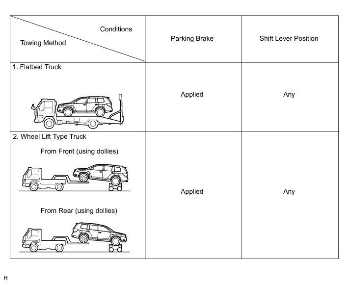
NOTICE:
Do not use any towing method other than those shown above.
(c) If a tow truck is not available, in an emergency the vehicle may be temporarily towed using a cable or chain secured to the emergency towing eyelet(s).
This should only be attempted on hard surfaced roads for distances of less than 80 km, and at speeds below 30km/h (19 mph).
A driver must be in the vehicle to steer and operate the brakes. The vehicle's wheels, drivetrain, axles, steering and brakes must be in good condition.
NOTICE:
If the towing speed or distance exceeds the above limits, or the vehicle is towed in a backward direction with any of the wheels on the ground, the drivetrain may be damaged.
(1) Emergency towing procedure
1 Turn the ignition switch to ON.
2 Depress the brake pedal and move the transmission shift lever to N.
3 Release the parking brake.
4 Release the brake pedal slowly.
NOTICE:
* Use extreme caution when towing the vehicle. Avoid sudden starts or erratic driving maneuvers which place excessive stress on the emergency towing eyelet and the cables or chains.
* Do not turn off the ignition switch. Turning off the ignition switch may result in engagement of the steering lock, resulting in a hazardous situation or accident.
(d) The towing methods shown below are dangerous and can damage the vehicle, so do not use them.
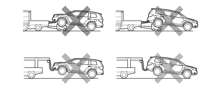
(1) Do not tow the vehicle with only 2 wheels on the ground.
NOTICE:
If the vehicle is towed with only the 2 wheels on the ground, the drivetrain may overheat and be damaged or the wheels may come off the dollies.
(2) Do not use a sling-type towing method either from the front or rear.
NOTICE:
If a sling-type tow truck is used, damage may occur to the vehicle body.
16. FOR VEHICLES EQUIPPED WITH CATALYTIC CONVERTER
CAUTION:
If a large amount of unburned gasoline or gasoline vapors flow into the converter, it may cause overheating and create a fire hazard. To prevent this, observe the following precautions:
(a) Use only unleaded gasoline.
(b) Avoid performing unnecessary spark tests.
(1) Perform a spark test only when absolutely necessary. Perform this test as rapidly as possible with the injector connector disconnected.
(c) While testing, never race the engine unless instructed.
(d) Do not run the engine when the fuel tank is nearly empty. This may cause the engine to misfire and create an extra load on the converter.
17. EXPRESSIONS OF IGNITION SWITCH
(a) The type of ignition switch used on this model differs according to the specifications of the vehicle. The expressions listed in the table below are used in this section.