Installation
HYBRID / BATTERY CONTROL: ELECTRIC VEHICLE CHARGER ASSEMBLY: INSTALLATION
1. INSTALL ELECTRIC VEHICLE CHARGER SUB-ASSEMBLY
CAUTION:
Wear insulated gloves.
(a) Install the plug-in charge control ECU assembly with the 2 nuts to the electric vehicle charger sub-assembly.
Torque : 5.5 Nm (56 kgf-cm, 49 in-lbf)
(b) Connect the connector.
(c) Install the electric vehicle charger sub-assembly to the electric vehicle charger bracket as shown in the illustration.
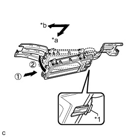
NOTICE:
* Do not drop the electric vehicle charger sub-assembly.
* Support the electric vehicle charger sub-assembly using an attachment or similar item to ensure that it does not fall.
* Connect the bracket of the electric vehicle charger sub-assembly to the electric vehicle charger bracket.
* Do not damage the wire harness of the electric vehicle charger sub-assembly using the electric vehicle charger bracket.
Text in Illustration

(d) Install the 4 bolts.
Torque : 8.0 Nm (82 kgf-cm, 71 in-lbf)
2. CONNECT ELECTRIC VEHICLE CHARGE CONNECTOR BRACKET
CAUTION:
Wear insulated gloves.
(a) Install the electric vehicle charge connector bracket with the 2 bolts.
Torque : 8.0 Nm (82 kgf-cm, 71 in-lbf)
(b) Connect the 2 clamps.
(c) Connect the 2 connectors and slide the 2 green-colored locks in the direction indicated by the arrow in the illustration to lock them securely.
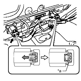
Text in Illustration

NOTICE:
Make sure that the connectors are connected securely.
(d) Connect the clamp.
(e) Connect the 2 connectors and clamp.
3. INSTALL HYBRID BATTERY HOSE ASSEMBLY Installation
4. INSTALL BATTERY COOLING BLOWER ASSEMBLY (for RH Side) Installation
5. INSTALL BATTERY COOLING BLOWER ASSEMBLY (for LH Side) Installation
6. INSTALL REAR DECK TRIM COVER Installation
7. INSTALL DECK TRIM SERVICE HOLE COVER Installation
8. INSTALL DECK FLOOR BOX LH
HINT
Use the same procedure described for the RH side Installation.
9. INSTALL REAR NO. 4 FLOOR BOARD SUB-ASSEMBLY Installation
10. INSTALL REAR NO. 2 FLOOR BOARD Installation
11. INSTALL SERVICE PLUG GRIP
Installation