Pattern Select Switch ECO Mode Circuit
HYBRID / BATTERY CONTROL: HYBRID CONTROL SYSTEM: Pattern Select Switch Eco Mode Circuit
- Pattern Select Switch Eco Mode Circuit
DESCRIPTION
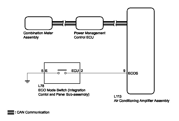
When selecting ECO drive mode, the ECO mode switch (integration control and panel sub-assembly) operation signal is sent to the air conditioning amplifier assembly. Following this, ECO drive mode control is activated for the heater and air conditioning system.
WIRING DIAGRAM
INSPECTION PROCEDURE
PROCEDURE
1. READ VALUE USING TECHSTREAM (CAN BUS CHECK) Pattern Select Switch EV/HV Mode Circuit
B -- GO TO CAN COMMUNICATION SYSTEM How to Proceed With Troubleshooting
A -- Continue to next step.
2. CHECK DTC OUTPUT (HEALTH CHECK) Pattern Select Switch EV/HV Mode Circuit
B -- GO TO DTC CHART
A -- Continue to next step.
3. PERFORM ACTIVE TEST USING TECHSTREAM (INDICAT. ECO MODE)
(a) Connect the Techstream to the DLC3.
(b) Turn the power switch on (IG).
(c) Enter the following menus: Body Electrical / Combination Meter / Active Test / Indicat. ECO Mode.
(d) Perform the "Indicat. ECO MODE" Active Test.
OK:
The ECO MODE indicator lamp comes on or blinks.
(e) Turn the power switch off.
NG -- REPLACE NO. 2 METER CIRCUIT PLATE Components
OK -- Continue to next step.
4. READ VALUE USING TECHSTREAM (ECO MODE)
(a) Connect the Techstream to the DLC3.
(b) Turn the power switch on (IG).
(c) Enter the following menus: Powertrain / Hybrid Control / Data List / ECO Mode.
(d) Read the value displayed on the Techstream.
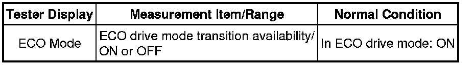
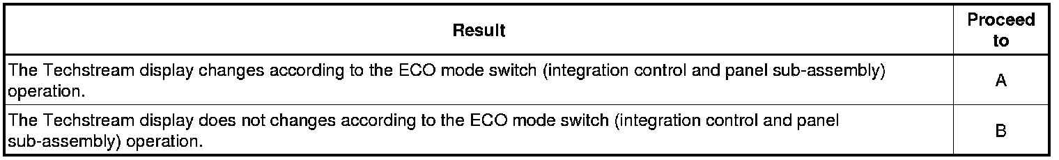
Result:

B -- READ VALUE USING TECHSTREAM (ECO SWITCH)
A -- CHECK FOR INTERMITTENT PROBLEMS Check for Intermittent Problems
5. READ VALUE USING TECHSTREAM (ECO SWITCH)
(a) Connect the Techstream to the DLC3.
(b) Turn the power switch on (IG).
(c) Enter the following menus: Body Electrical / Air Conditioning / Data List / ECO Switch.
(d) Read the value displayed on the Techstream.
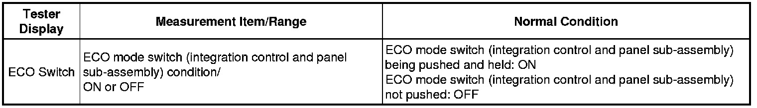
Result:
B -- CHECK ECO MODE SWITCH (INTEGRATION CONTROL AND PANEL SUB-ASSEMBLY)
A -- REPLACE AIR CONDITIONING AMPLIFIER ASSEMBLY Removal
6. CHECK ECO MODE SWITCH (INTEGRATION CONTROL AND PANEL SUB-ASSEMBLY)
(a) Remove the ECO mode switch (integration control and panel sub-assembly).
(b) Measure the resistance according to the value(s) in the table below.
Standard Resistance:

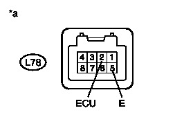
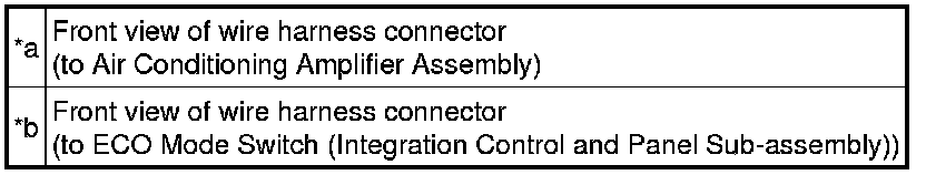
Text in Illustration
(c) Install the ECO mode switch (integration control and panel sub-assembly).
NG -- REPLACE ECO MODE SWITCH (INTEGRATION CONTROL AND PANEL SUB-ASSEMBLY) Components
OK -- Continue to next step.
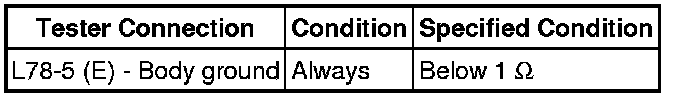
7. CHECK HARNESS AND CONNECTOR (ECO MODE SWITCH (INTEGRATION CONTROL AND PANEL SUB-ASSEMBLY) - BODY GROUND)
(a) Disconnect connector L78 from the ECO mode switch (integration control and panel sub-assembly).
(b) Measure the resistance according to the value(s) in the table below.

Standard Resistance:
Text in Illustration
(c) Connect the ECO mode switch (integration control and panel sub-assembly) connector.
NG -- REPAIR OR REPLACE HARNESS OR CONNECTOR
OK -- Continue to next step.
8. CHECK HARNESS AND CONNECTOR (AIR CONDITIONING AMPLIFIER ASSEMBLY - COMBINATION SWITCH)
(a) Disconnect connector L113 from the air conditioning amplifier assembly.
(b) Disconnect connector L78 from the ECO mode switch (integration control and panel sub-assembly).
(c) Measure the resistance according to the value(s) in the table below.
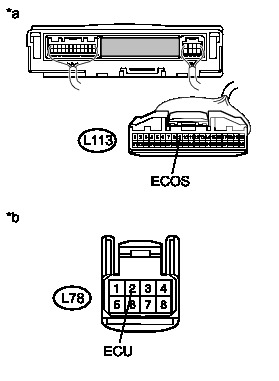
Standard Resistance:
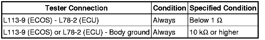
Text in Illustration
(d) Connect the ECO mode switch (integration control and panel sub-assembly) connector.
(e) Connect the air conditioning amplifier assembly connector.
NG -- REPAIR OR REPLACE HARNESS OR CONNECTOR
OK -- REPLACE AIR CONDITIONING AMPLIFIER ASSEMBLY Removal