How To Proceed With Troubleshooting
HYBRID / BATTERY CONTROL: PLUG-IN CHARGE CONTROL SYSTEM: HOW TO PROCEED WITH TROUBLESHOOTING
HINT
* *: Use the Techstream
* Use the following procedure to troubleshoot the plug-in charge control system.
1. VEHICLE BROUGHT TO WORKSHOP
NEXT -- Continue to next step.
2. CUSTOMER PROBLEM ANALYSIS
NEXT -- Continue to next step.
3. CONNECT TECHSTREAM TO THE DLC3*
HINT
If the display on the tester indicates a communication fault, inspect the DLC3.
NEXT -- Continue to next step.
4. CHECK DTC AND SAVE FREEZE FRAME DATA* Plug-In Charge Control System
HINT
* If any of the CAN communication system DTCs is output, troubleshoot and repair the CAN communication system first How to Proceed With Troubleshooting.
* If the Freeze Frame Data item "On-Board Charger Input Voltage" shows 270 V or more, there is a possibility that the charging voltage was higher than standard voltage, causing a DTC to be output. When performing a reproduction test, plug-in charge the vehicle at the standard voltage (100 to 240 V), then check for DTCs.
NEXT -- Continue to next step.
5. CHECK CHARGE CANCEL HISTORY Plug-In Charge Control System
NEXT -- Continue to next step.
6. CLEAR DTC AND FREEZE FRAME DATA* Plug-In Charge Control System
NEXT -- Continue to next step.
7. CONDUCT VISUAL INSPECTION
NEXT -- Continue to next step.
8. CONFIRM PROBLEM SYMPTOMS
Result:
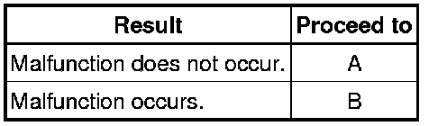
B -- GO TO STEP 11
A -- Continue to next step.
9. DUPLICATE CONDITIONS THAT PRODUCE SYMPTOMS
NEXT -- Continue to next step.
10. CHECK FOR DTCS* Plug-In Charge Control System
Result:
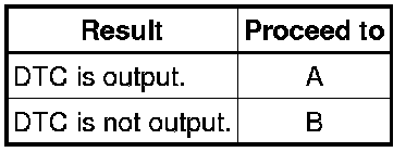
B -- GO TO STEP 12
A -- Continue to next step.
11. REFER TO DTC CHART Plug-In Charge Control System
HINT
DTCs for the hybrid control system and hybrid battery system are displayed using the same menus on the Techstream. It is necessary to check the DTC charts for hybrid control system and hybrid battery system.
* Hybrid Control System - DTC chart Hybrid Control System
* Hybrid Battery System - DTC chart Hybrid Battery System
NEXT -- GO TO STEP 14
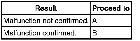
12. CONDUCT BASIC INSPECTION
Result:
B -- GO TO STEP 16
A -- Continue to next step.
13. CHECK ECU POWER SOURCE CIRCUIT
NEXT -- Continue to next step.
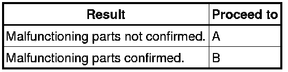
14. CONDUCT CIRCUIT INSPECTION
Result:
B -- GO TO STEP 17
A -- Continue to next step.
15. CHECK FOR INTERMITTENT PROBLEMS Check For Intermittent Problems
NEXT -- GO TO STEP 17
16. CONDUCT PARTS INSPECTION
NEXT -- Continue to next step.
17. IDENTIFY PROBLEM
NEXT -- Continue to next step.
18. ADJUST AND/OR REPAIR
NEXT -- Continue to next step.
19. CONDUCT CONFIRMATION TEST
NEXT -- END