Installation
SUPPLEMENTAL RESTRAINT SYSTEMS: CENTER AIRBAG SENSOR ASSEMBLY: INSTALLATION
1. INSTALL AIRBAG ECU ASSEMBLY
(a) Check that the power switch is off.
(b) Check that the cable is disconnected from the negative (-) auxiliary battery terminal.
CAUTION:
Wait at least 90 seconds after disconnecting the cable from the negative (-) auxiliary battery terminal to disable the SRS system.
(c) Using SST, install the airbag ECU assembly with the 3 bolts.
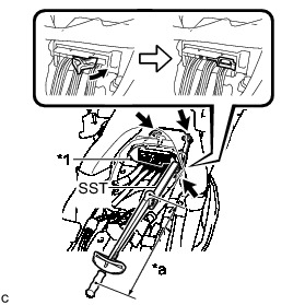
Text in Illustration
SST : 09961-00950
without SST - Torque : 18 Nm (178 kgf-cm, 13 ft-lbf)
with SST - Torque : 11 Nm (112 kgf-cm, 8 ft-lbf)
NOTICE:
* Use a torque wrench with a fulcrum length of 250 mm (9.84 in.).
* This torque value is effective when SST is parallel to a torque wrench.
* If the airbag ECU assembly has been dropped, or there are any cracks, dents or other defects in the case or connector, replace it with a new one.
* When installing the airbag ECU assembly, be careful that the SRS wiring does not interfere with or is not pinched between other parts.
* When the power switch is first turned on (IG) after the airbag ECU assembly has been replaced, make sure that no one is in the vehicle.
(d) Connect the connectors to the airbag ECU assembly as shown in the illustration.
NOTICE:
When connecting any airbag connector, take care not to damage the airbag wire harness.
(e) Check that the waterproof sheet is properly set.
(f) Check that there is no looseness in the installation parts of the airbag ECU assembly.
2. INSTALL CONSOLE BOX ASSEMBLY Installation
3. INSTALL UPPER INSTRUMENT PANEL FINISH PANEL ASSEMBLY Installation
4. INSTALL BOX BOTTOM MAT Installation
5. INSTALL FRONT NO. 2 CONSOLE BOX INSERT Installation
6. INSTALL CONSOLE BOX INSERT Installation
7. INSTALL NO. 2 CONSOLE BOX MOUNTING BRACKET Installation
8. INSTALL NO. 1 INDOOR ELECTRICAL KEY ANTENNA ASSEMBLY Installation
9. INSTALL SHIFT LOCK CONTROL UNIT ASSEMBLY Installation
10. INSTALL AIR CONDITIONING CONTROL ASSEMBLY Installation
11. INSTALL GLOVE COMPARTMENT DOOR Installation
12. INSTALL NO. 2 INSTRUMENT PANEL REGISTER Installation
13. INSTALL NO. 1 SIDE DEFROSTER NOZZLE Installation
14. INSTALL RADIO AND DISPLAY RECEIVER ASSEMBLY WITH BRACKET (w/o Navigation System) Installation
15. INSTALL NAVIGATION RECEIVER WITH BRACKET (w/ Navigation System) Installation
16. INSTALL UPPER INSTRUMENT PANEL FINISH PANEL SUB-ASSEMBLY Installation
17. INSTALL INSTRUMENT CLUSTER FINISH PANEL GARNISH Installation
18. INSTALL LOWER CENTER INSTRUMENT CLUSTER FINISH PANEL SUB-ASSEMBLY Installation
19. INSTALL INTEGRATION CONTROL AND PANEL ASSEMBLY Installation
20. INSTALL REAR CONSOLE BOX ASSEMBLY
Installation
21. CONNECT CABLE TO NEGATIVE AUXILIARY BATTERY TERMINAL
NOTICE:
When disconnecting the cable, some systems need to be initialized after the cable is reconnected Repair Instruction - Initialization.
22. INSTALL REAR NO. 3 FLOOR BOARD UPPER PLATE Installation
23. INSTALL DECK FLOOR BOX RH Installation
24. INSTALL REAR NO. 3 FLOOR BOARD Installation
25. PERFORM DIAGNOSTIC SYSTEM CHECK
DTC Check / Clear
26. INSPECT SRS WARNING LIGHT
Diagnosis System