Part 3
U241E AUTOMATIC TRANSAXLE: AUTOMATIC TRANSAXLE UNIT: REASSEMBLY - Continued
52. INSTALL C-3 ACCUMULATOR PISTON
(a) Coat a new O-ring with ATF, and install it to the C-3 accumulator piston.
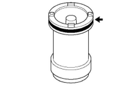
(b) Coat the C-3 accumulator piston with ATF, and install it to the transaxle.
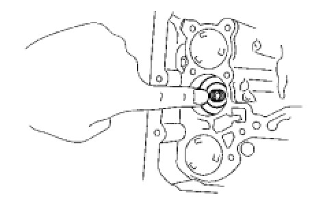
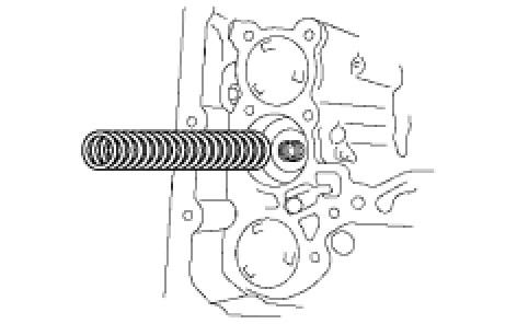
(c) Install the compression spring from the C-3 accumulator piston.
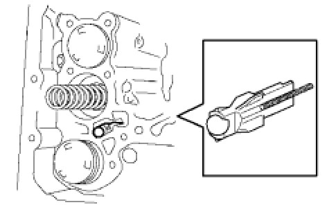
53. INSTALL CHECK BALL BODY
(a) Install the check ball body and spring.
54. INSTALL TRANSMISSION WIRE
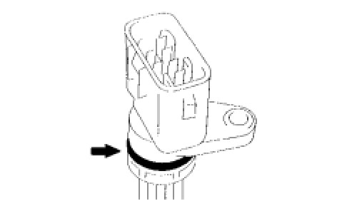
(a) Coat a new O-ring with ATF, and install it to the transaxle solenoid wire.
(b) Install the solenoid wire retaining bolt.
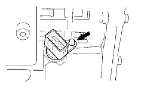
Torque : 5.4 Nm (55 kgf-cm, 48 in-lbf)
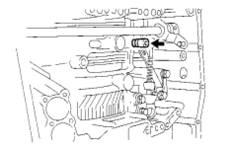
55. INSTALL BRAKE DRUM GASKET
(a) Coat a new brake drum gasket with ATF, and install it to the transaxle.
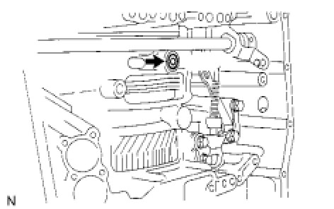
56. INSTALL TRANSAXLE CASE 2ND BRAKE GASKET
(a) Coat a new transaxle case 2nd brake gasket with ATF, and install it to the transaxle.
57. INSTALL NO. 1 GOVERNOR APPLY GASKET
(a) Coat a new governor apply gasket No. 1 with ATF, and install it to the transaxle.
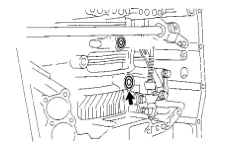
58. INSTALL TRANSMISSION VALVE BODY ASSEMBLY
(a) Make sure that the manual valve lever position, install the valve body with the 17 bolts to the transaxle.
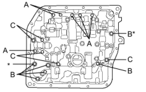
Torque : 11 Nm (112 kgf-cm, 8 ft-lbf)
HINT
Each bolt length is indicated below.
Bolt length:
25 mm (0.984 in.) for bolt A
41 mm (1.614 in.) for bolt B
45 mm (1.771 in.) for bolt C
NOTICE:
* Push the valve body against the accumulator piston spring and the check ball body to install it.
* When installing the valve body to the transaxle case, do not hold the solenoids.
* Tighten the bolts marked by * in the illustration first temporarily because they are positioning bolts.
(b) Connect the 5 solenoid connectors.
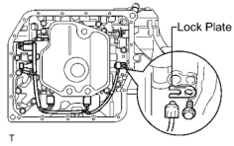
(c) Install the ATF temperature sensor, clamp and bolt.
Torque : 6.6 Nm (67 kgf-cm, 58 in-lbf)
59. INSTALL VALVE BODY OIL STRAINER ASSEMBLY
(a) Coat a new O-ring with ATF, and install it to the oil strainer.
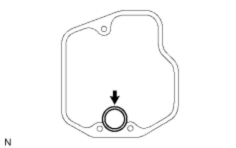
(b) Install the oil strainer and 3 bolts to the valve body.
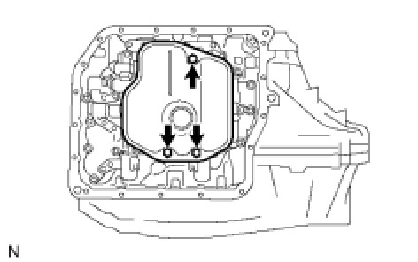
Torque : 11 Nm (112 kgf-cm, 8 ft-lbf)
60. INSTALL AUTOMATIC TRANSAXLE OIL PAN SUB-ASSEMBLY
(a) Install the 3 magnets in the oil pan.

(b) Install a new oil pan gasket to the oil pan.
(c) Install the oil pan to the transaxle with the 18 bolts.
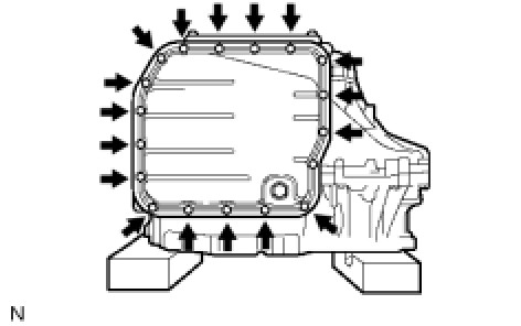
Torque : 7.6 Nm (77 kgf-cm, 67 in-lbf)
NOTICE:
Because the bolts are seal bolts, apply seal packing to new bolts and tighten them within 10 minutes after application.
61. INSTALL SPEED SENSOR
(a) Coat 2 new O-rings with ATF, and install them to the 2 sensors.
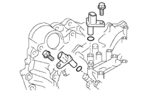
(b) Install the 2 sensors with the 2 bolts to the transaxle.
Torque : 11 Nm (112 kgf-cm, 8 ft-lbf)
62. INSTALL OIL COOLER INLET TUBE UNION
(a) Coat a new O-ring with ATF, and install it to the union.
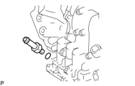
(b) Install the union to the transaxle.
Torque : 27 Nm (276 kgf-cm, 20 ft-lbf)
63. INSTALL OIL COOLER OUTLET TUBE UNION
(a) Coat a new O-ring with ATF, and install it to the union.
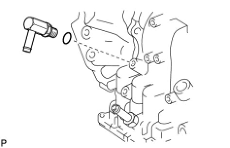
(b) Install the union to the transaxle case.
Torque : 25 Nm (255 kgf-cm, 18 ft-lbf)
64. INSTALL NO. 1 TRANSAXLE CASE PLUG
(a) Coat 4 new O-rings with ATF, and install them to the 4 plugs.
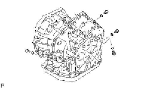
(b) Install the 4 plugs to the transaxle.
Torque : 7.4 Nm (75 kgf-cm, 65 in-lbf)
65. INSTALL BREATHER PLUG HOSE
(a) Install the breather plug hose to the breather plug.
66. INSTALL PARK/NEUTRAL POSITION SWITCH ASSEMBLY
(a) Install the park/neutral position switch onto the manual valve lever shaft and temporarily install the 2 adjusting bolts.
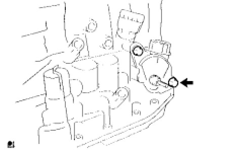
(b) Install a new lock plate and the nut.
Torque : 5.4 Nm (55 kgf-cm, 48 in-lbf)
(c) Temporarily install the control shaft lever.
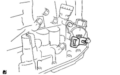
(d) Turn the lever counterclockwise until it stops, and then turn it clockwise 2 notches.
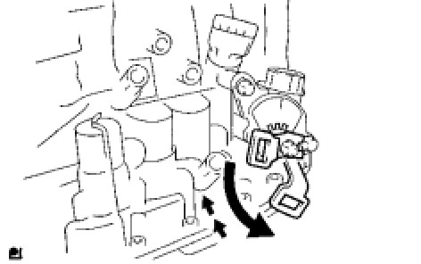
(e) Remove the control shaft lever.
(f) Align the groove with neutral basic line.

(g) Tighten the 2 bolts.
Torque : 6.9 Nm (70 kgf-cm, 61 in-lbf)
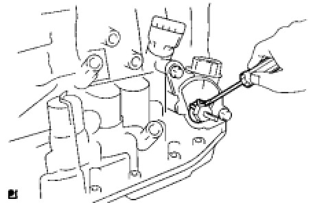
(h) Using a screwdriver, stake the nut with the lock plate.
(i) Install the control shaft lever, washer and nut.
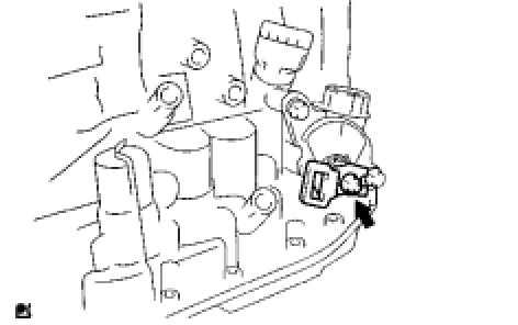
Torque : 13 Nm (133 kgf-cm, 10 ft-lbf)
67. INSTALL SPEEDOMETER DRIVEN HOLE COVER SUB-ASSEMBLY
(a) Coat a new O-ring with ATF and install it to the hole cover.
(b) Install the hole cover to the transaxle with the bolt.