Part 3
U140F AUTOMATIC TRANSAXLE: AUTOMATIC TRANSAXLE UNIT: REASSEMBLY - Continued
44. INSTALL MANUAL VALVE LEVER SHAFT OIL SEAL
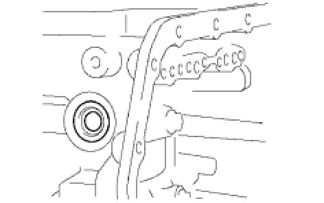
(a) Coat a new oil seal with ATF.
(b) Install the oil seal to the transaxle.
45. INSTALL PARKING LOCK ROD SUB-ASSEMBLY
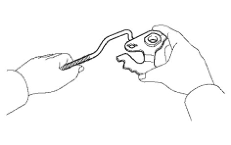
(a) Install the parking lock rod to the manual valve lever.
46. INSTALL MANUAL VALVE LEVER SUB-ASSEMBLY
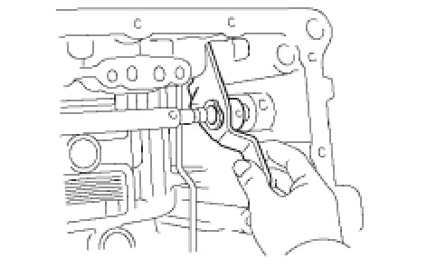
(a) Install a new spacer and manual valve lever shaft to the transaxle.
(b) Using a pin punch and hammer, tap in a new pin.
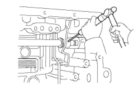
(c) Turn the spacer and lever shaft to align the small hole for locating the staking position mark on the lever shaft.
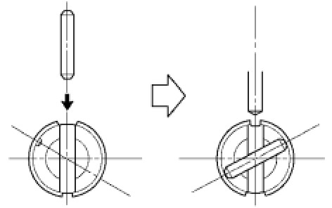
(d) Using a pin punch, stake the spacer through the small hole.
(e) Check that the spacer does not turn.
47. INSTALL MANUAL VALVE LEVER SHAFT RETAINER SPRING
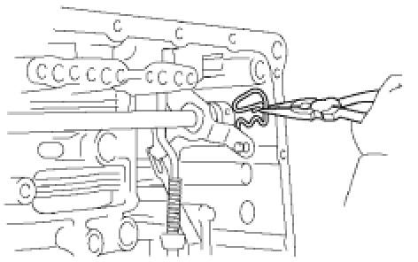
(a) Using needle-nose pliers, install the retainer spring.
48. INSTALL PARKING LOCK PAWL BRACKET
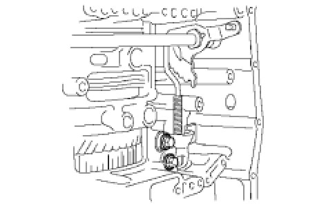
(a) Install the parking lock pawl bracket with the 2 bolts.
Torque : 20 Nm (205 kgf-cm, 15 ft-lbf)
Bolt length:
25 mm (0.984 in.)
49. INSTALL MANUAL DETENT SPRING SUB-ASSEMBLY
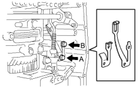
(a) Install the manual detent spring with the 2 bolts.
NOTICE:
Make sure to install the manual detent spring and cover in this order.
Torque : 20 Nm (204 kgf-cm, 16 ft-lbf) for bolt A
Torque : 12 Nm (122 kgf-cm, 9 ft-lbf) for bolt B
HINT
Each bolt length is indicated below.
* 27 mm (1.063 in.) for bolt A
* 16 mm (0.630 in.) for bolt B
50. INSTALL B-3 ACCUMULATOR PISTON
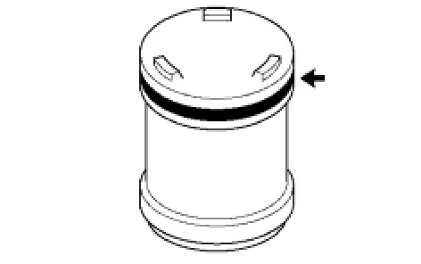
(a) Coat a new O-ring with ATF, and install it to the B-3 accumulator piston.
(b) Coat the piston with ATF, install it to the transaxle.
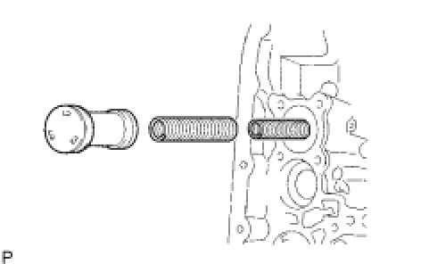
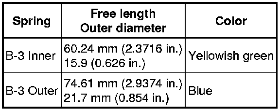
Standard accumulator spring:
51. INSTALL C-1 ACCUMULATOR PISTON
(a) Coat 2 new O-rings with ATF, and install them to the C-1 accumulator piston.
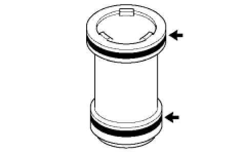
(b) Coat the piston with ATF, and install it to the transaxle.
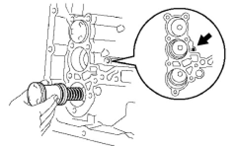
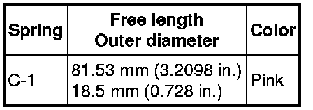
Standard accumulator spring:
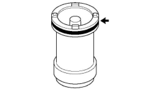
52. INSTALL C-3 ACCUMULATOR PISTON
(a) Coat a new O-ring with ATF, and install it to the C-3 accumulator piston.
(b) Coat the piston with ATF, install it to the transaxle case.
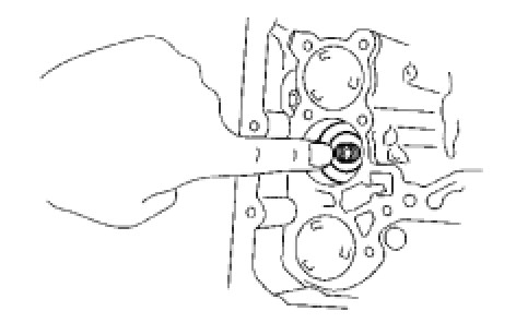
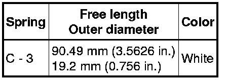
Standard accumulator spring:
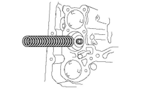
(c) Install the spring from the C-3 accumulator piston.
53. INSTALL CHECK BALL BODY
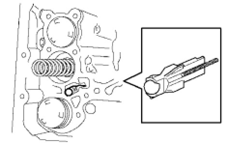
(a) Install the check ball body and spring.
54. INSTALL BRAKE DRUM GASKET
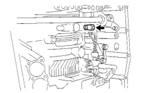
(a) Coat a new brake drum gasket with ATF, and install it to the transaxle.
55. INSTALL TRANSAXLE CASE 2ND BRAKE GASKET
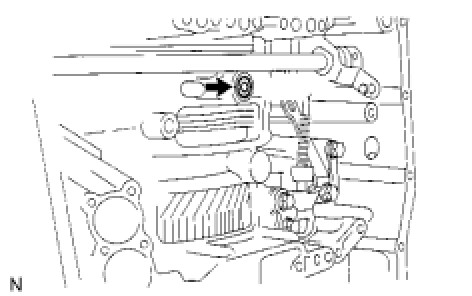
(a) Coat a new transaxle case 2nd brake gasket with ATF, and install it to the transaxle.
56. INSTALL NO. 1 GOVERNOR APPLY GASKET
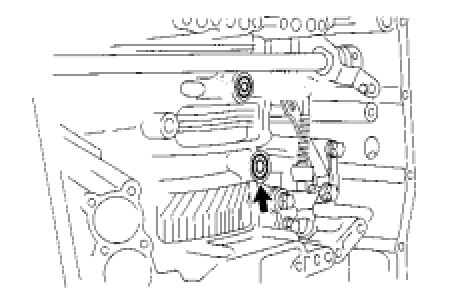
(a) Coat a new governor apply gasket No. 1 with ATF, and install it to the transaxle.
57. INSTALL TRANSMISSION WIRE
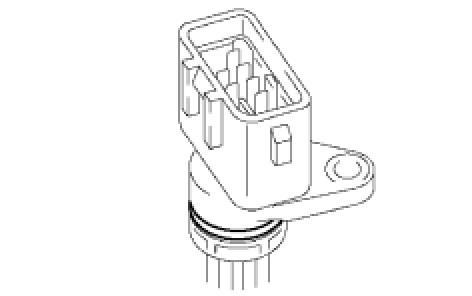
(a) Coat a new O-ring with ATF, and install it to the transaxle solenoid wire.
(b) Install the solenoid wire retaining bolt
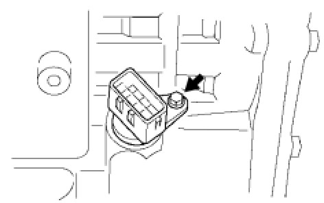
Torque : 5.4 Nm (55 kgf-cm, 48 in-lbf)
58. INSTALL TRANSMISSION VALVE BODY ASSEMBLY
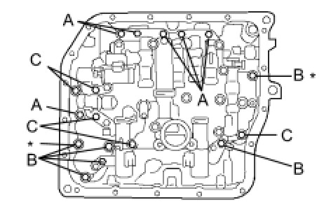
(a) Align the groove of the manual valve with the pin of lever.
(b) Install the 17 bolts.
Torque : 11 Nm (112 kgf-cm, 8 ft-lbf)
NOTICE:
* Push the valve body against the accumulator piston spring and the check ball body to install it.
* Tighten the bolts marked by * in the illustration first temporarily because they are positioning bolts.
HINT
Each bolt length is indicated below.
Bolt length:
25 mm (0.984 in.) for bolt A
41 mm (1.614 in.) for bolt B
45 mm (1.771 in.) for bolt C
(c) Connect the 5 solenoid connectors.
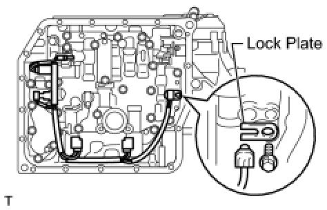
(d) Coat the O-ring of the temperature sensor with ATF.
(e) Install the ATF temperature sensor with the lock plate and bolt.
Torque : 6.6 Nm (67 kgf-cm, 58 in-lbf)
59. INSTALL VALVE BODY OIL STRAINER ASSEMBLY
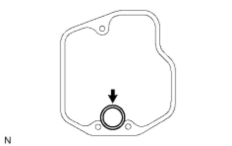
(a) Coat a new O-ring with ATF.
(b) Install the O-ring to the oil strainer.
(c) Install the oil strainer with the 3 bolts.
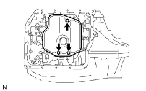
Torque : 11 Nm (112 kgf-cm, 8 ft-lbf)
60. INSTALL AUTOMATIC TRANSAXLE OIL PAN SUB-ASSEMBLY
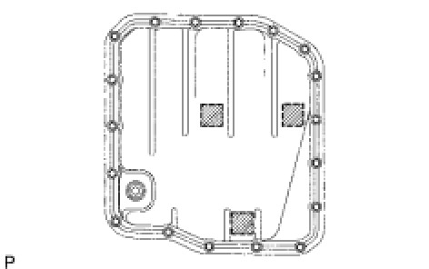
(a) Install the 3 magnets in the oil pan.
(b) Install a new oil pan gasket to the oil pan.
(c) Install the oil pan to the transaxle with the 18 bolts.
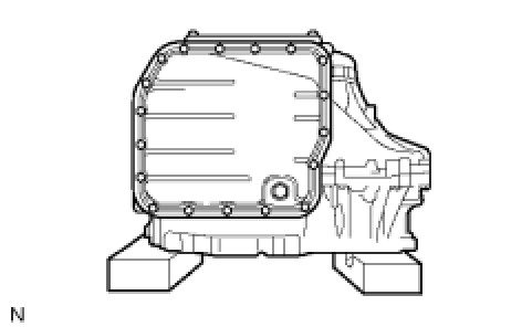
Torque : 7.6 Nm (77 kgf-cm, 67 in-lbf)
NOTICE:
Because the bolts are seal bolts, apply seal packing to new bolts and tighten them within 10 minutes after application.
61. INSTALL NO. 1 TRANSAXLE CASE PLUG
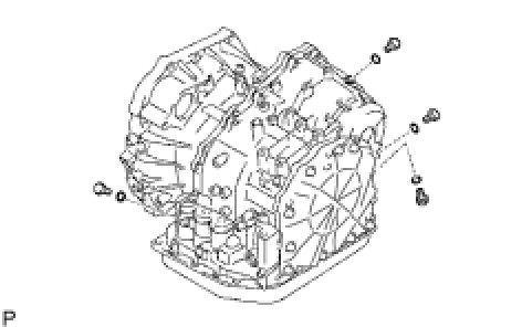
(a) Coat 4 new O-rings with ATF, and install them to the 4 plugs.
(b) Install the 4 plugs to the transaxle case.
Torque : 7.4 Nm (75 kgf-cm, 65 in-lbf)
62. INSTALL SPEED SENSOR
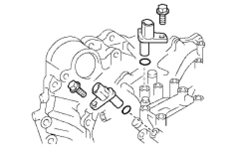
(a) Coat 2 new O-rings with ATF, and install them to the 2 sensors.
(b) Install the 2 sensors with the 2 bolts.
Torque : 11 Nm (112 kgf-cm, 8 ft-lbf)
63. INSTALL OIL COOLER INLET TUBE UNION
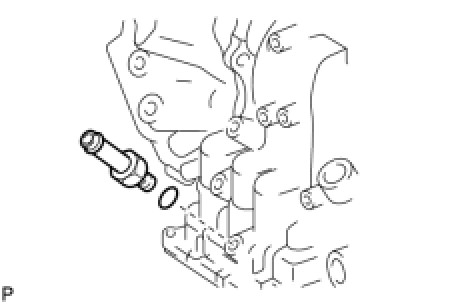
(a) Coat a new O-ring with ATF, and install it to the union.
(b) Install the union to the transaxle.
Torque : 27 Nm (276 kgf-cm, 20 ft-lbf)
64. INSTALL OIL COOLER OUTLET TUBE UNION
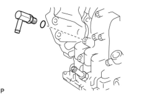
(a) Coat a new O-ring with ATF, and install it to the union.
(b) Install the union to the transaxle.
Torque : 25 Nm (255 kgf-cm, 18 ft-lbf)
65. INSTALL BREATHER PLUG HOSE
66. INSTALL PARK/NEUTRAL POSITION SWITCH ASSEMBLY
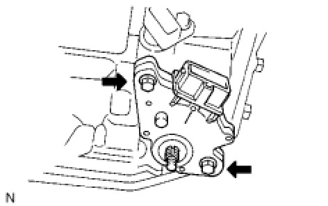
(a) Install the park/neutral position switch to the manual valve shaft.
(b) Temporarily install the 2 bolts.
(c) Install a new lock plate and tighten the manual valve shaft nut.
Torque : 5.4 Nm (55 kgf-cm, 48 in-lbf)
(d) Temporarily install the control shaft lever.
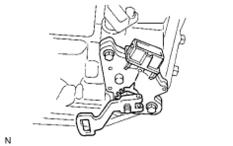
(e) Turn the lever counterclockwise until it stops, and then turn it clockwise 2 notches.
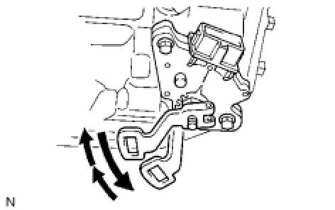
(f) Remove the control shaft lever.
(g) Align the groove with neutral basic line.

(h) Hold the switch in this position and tighten the 2 bolts.
Torque : 6.9 Nm (70 kgf-cm, 61 in-lbf)
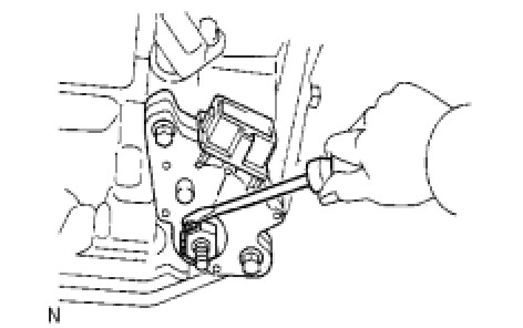
(i) Using a screwdriver, stake the nut with the lock plate.
(j) Install the control shaft lever with the washer and nut.
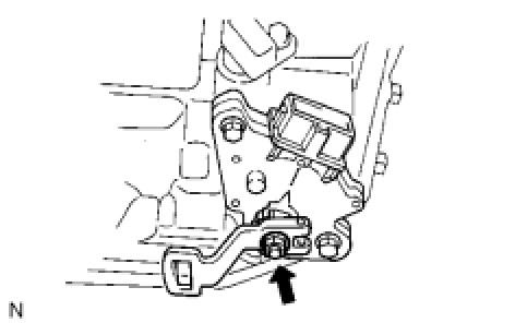
Torque : 13 Nm (133 kgf-cm, 10 ft-lbf)