Fuel Injection System
3UR-FBE ENGINE CONTROL: SFI SYSTEM: Fuel Injection System
- Fuel Injection System
DESCRIPTION
This inspection procedure should be performed when the air-fuel ratio is extremely rich or lean.
INSPECTION PROCEDURE
PROCEDURE
1. CHECK PCV HOSE CONNECTIONS
(a) Check the PCV hose connections Testing and Inspection.
OK:
PCV hose is connected correctly and is not damaged.
NG -- REPAIR OR REPLACE PCV HOSE
OK -- Continue to next step.
2. CHECK AIR INDUCTION SYSTEM
(a) Check the air induction system for vacuum leakage Intake System.
OK:
No leakage from air induction system.
NG -- REPAIR OR REPLACE AIR INDUCTION SYSTEM
OK -- Continue to next step.
3. PERFORM ACTIVE TEST USING TECHSTREAM (CONTROL THE INJECTION VOLUME)
(a) Connect the Techstream to the DLC3.
(b) Start the engine.
(c) Turn the Techstream on.
(d) Warm up the engine and run the engine at an engine speed of 2500 rpm for approximately 90 seconds.
(e) Enter the following menus: Powertrain / Engine and ECT / Active Test / Control the Injection Volume for A/F Sensor.
(f) Perform the Control the Injection Volume operation with the engine idling.
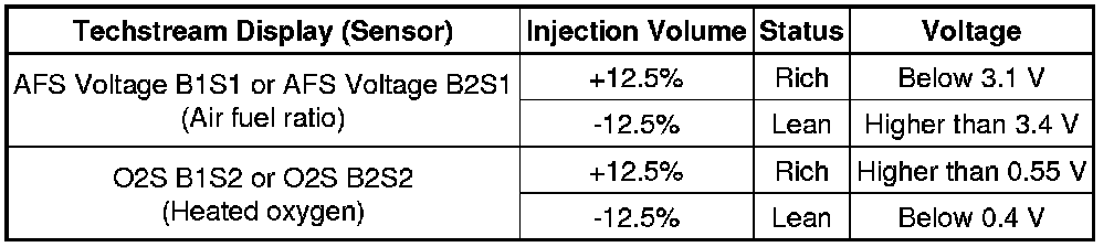
(g) Monitor the output voltages of the air fuel ratio and heated oxygen sensors (AFS Voltage B1S1 and O2S B1S2 or AFS Voltage B2S1 and O2S B2S2) displayed on the Techstream.
HINT
* Change the fuel injection volume within the range of - 12.5% to +12.5%. The injection volume can be changed in fine gradations.
* The air fuel ratio sensor has an output delay of a few seconds and the heated oxygen sensor has a maximum output delay of approximately 20 seconds.
* If the sensor output voltage does not change (almost no reaction) while performing the Active Test, the sensor may be malfunctioning.
Result
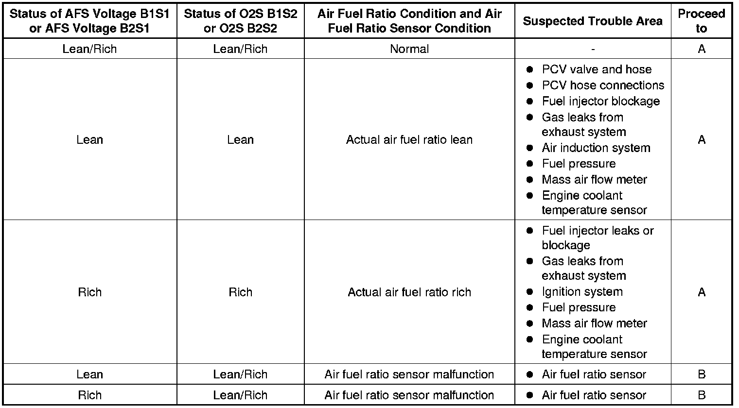
Lean: During the Control the Injection Volume for A/F Sensor Active Test, the air fuel ratio sensor output voltage (AFS Voltage) is consistently higher than 3.4 V, and the heated oxygen sensor output voltage (O2S) is consistently below 0.4 V.
Rich: During the Control the Injection Volume for A/F Sensor Active Test, the AFS Voltage is consistently below 3.1 V, and the O2S is consistently higher than 0.55 V.
Lean/Rich: During the Control the Injection Volume for A/F Sensor Active Test, the output voltage of the heated oxygen sensor alternates correctly.
B -- INSPECT AIR FUEL RATIO SENSOR (HEATER RESISTANCE)
A -- Continue to next step.
4. READ VALUE USING TECHSTREAM (COOLANT TEMP)
(a) Connect the Techstream to the DLC3.
(b) Turn the ignition switch to ON.
(c) Turn the Techstream on.
(d) Enter the following menus: Powertrain / Engine and ECT / Data List / All Data / Coolant Temp.
(e) Read the Coolant Temp twice, when the engine is both cold and warmed up.
Standard:
With cold engine: Same as ambient air temperature.
With warm engine: Between 75°C and 100°C (167°F and 212°F).
NG -- REPLACE ENGINE COOLANT TEMPERATURE SENSOR Removal
OK -- Continue to next step.
5. READ VALUE USING TECHSTREAM (MAF)
(a) Connect the Techstream to the DLC3.
(b) Turn the ignition switch to ON.
(c) Turn the Techstream on.
(d) Enter the following menus: Powertrain / Engine and ECT / Data List / All Data / MAF and Coolant Temp.
(e) Allow the engine to idle until Coolant Temp reaches 75°C (167°F) or more.
(f) Read MAF with the engine speed at 3000 rpm.
Standard:
Between 18.0 gm/s and 27.0 gm/s (shift lever: N; A/C: Off).
NG -- CHECK HARNESS AND CONNECTOR
OK -- Continue to next step.
6. CHECK FUEL PRESSURE
(a) Check the fuel pressure Fuel System.
NG -- REPAIR OR REPLACE FUEL SYSTEM
OK -- Continue to next step.
7. CHECK FOR EXHAUST GAS LEAK
(a) Check for exhaust gas leak.
OK:
No gas leakage.
NG -- REPAIR OR REPLACE EXHAUST SYSTEM
OK -- Continue to next step.
8. CHECK FOR SPARKS AND IGNITION
(a) Perform a spark test Testing and Inspection.
HINT
If the result of the spark test is normal, proceed to the next step.
NEXT -- Continue to next step.
9. CHECK FUEL INJECTOR (INJECTION AND VOLUME)
(a) Check the injection and volume Testing and Inspection.
NG -- REPLACE FUEL INJECTOR Removal
OK -- Continue to next step.
10. CHECK FUEL PRESSURE SWITCHING SYSTEM
(a) Check the fuel pressure switching system Fuel Pressure Switching System.
HINT
If the problem area cannot be determined by checking the fuel pressure switching system, proceed to the next step.
NEXT -- CONFIRM WHETHER MALFUNCTION HAS BEEN SUCCESSFULLY REPAIRED
11. INSPECT AIR FUEL RATIO SENSOR (HEATER RESISTANCE) P0031
NG -- REPLACE AIR FUEL RATIO SENSOR Removal
OK -- Continue to next step.
12. CHECK TERMINAL VOLTAGE (+B OF AIR FUEL RATIO SENSOR) P0031
NG -- CHECK HARNESS AND CONNECTOR (AIR FUEL RATIO SENSOR - INTEGRATION RELAY)
OK -- Continue to next step.
13. CHECK HARNESS AND CONNECTOR (AIR FUEL RATIO SENSOR - ECM)
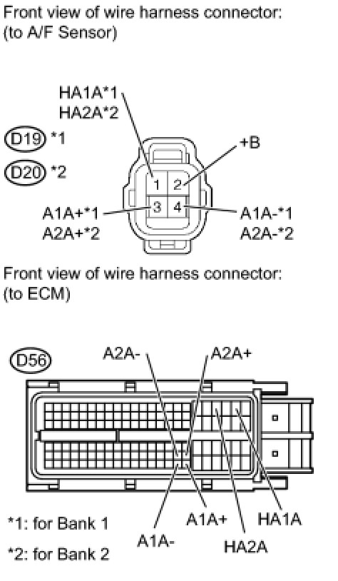
(a) Disconnect the D19 or D20 A/F sensor connector.
(b) Disconnect the D56 ECM connector.
(c) Measure the resistance according to the value(s) in the table below.
Standard resistance:
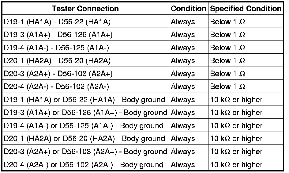
NG -- REPAIR OR REPLACE HARNESS OR CONNECTOR
OK -- Continue to next step.
14. REPLACE AIR FUEL RATIO SENSOR
(a) Replace the air fuel ratio sensor Removal.
NEXT -- Continue to next step.
15. CONFIRM WHETHER MALFUNCTION HAS BEEN SUCCESSFULLY REPAIRED
(a) Connect the Techstream to the DLC3.
(b) Turn the ignition switch to ON.
(c) Turn the Techstream on.
(d) Clear DTCs Reading and Clearing Diagnostic Trouble Codes.
(e) Turn the ignition switch off and wait for at least 30 seconds.
(f) Turn the ignition switch to ON and turn the Techstream on.
(g) Start the engine and warm it up.
(h) Drive the vehicle in accordance with the driving pattern described in the Confirmation Driving Pattern section of the DTC inspection procedure that was being performed before coming to this fuel injection system inspection procedure.
(i) Enter the following menus: Powertrain / Engine and ECT / Trouble Codes.
(j) Read DTCs.
Result

B -- END
A -- Continue to next step.
16. CHECK HARNESS AND CONNECTOR
(a) Check the connection and terminal contact pressure of the connectors and wire harnesses between the mass air flow meter and ECM Electronic Circuit Inspection Procedure.
HINT
Repair any problems.
NEXT -- Continue to next step.
17. CONFIRM WHETHER MALFUNCTION HAS BEEN SUCCESSFULLY REPAIRED
(a) Connect the Techstream to the DLC3.
(b) Turn the ignition switch to ON.
(c) Turn the Techstream on.
(d) Clear DTCs Reading and Clearing Diagnostic Trouble Codes.
(e) Turn the ignition switch off and wait for at least 30 seconds.
(f) Turn the ignition switch to ON and turn the Techstream on.
(g) Start the engine and warm it up.
(h) Drive the vehicle in accordance with the driving pattern described in the Confirmation Driving Pattern section of the DTC inspection procedure that was being performed before coming to this fuel injection system inspection procedure.
(i) Enter the following menus: Powertrain / Engine and ECT / Trouble Codes.
(j) Read DTCs.
Result

B -- END
A -- Continue to next step.
18. CHECK HARNESS AND CONNECTOR (MASS AIR FLOW METER - ECM) P0102
NG -- REPAIR OR REPLACE HARNESS OR CONNECTOR
OK -- Continue to next step.
19. REPLACE MASS AIR FLOW METER
(a) Replace the mass air flow meter Removal.
HINT
If the result of the inspection performed in step 5 indicated no problem, proceed to the next step without replacing the mass air flow meter.
NEXT -- Continue to next step.
20. CONFIRM WHETHER MALFUNCTION HAS BEEN SUCCESSFULLY REPAIRED
(a) Connect the Techstream to the DLC3.
(b) Turn the ignition switch to ON.
(c) Turn the Techstream on.
(d) Clear DTCs Reading and Clearing Diagnostic Trouble Codes.
(e) Turn the ignition switch off and wait for at least 30 seconds.
(f) Turn the ignition switch to ON and turn the Techstream on.
(g) Start the engine and warm it up.
(h) Drive the vehicle in accordance with the driving pattern described in the Confirmation Driving Pattern section of the DTC inspection procedure that was being performed before coming to this fuel injection system inspection procedure.
(i) Enter the following menus: Powertrain / Engine and ECT / Trouble Codes.
(j) Read DTCs.
Result

B -- REPLACE ECM Removal
A -- END
21. CHECK HARNESS AND CONNECTOR (AIR FUEL RATIO SENSOR - INTEGRATION RELAY) P0031
NG -- REPAIR OR REPLACE HARNESS OR CONNECTOR
OK -- Continue to next step.
22. INSPECT INTEGRATION RELAY (A/F) P0031
NG -- REPLACE INTEGRATION RELAY
OK -- CHECK ECM POWER SOURCE CIRCUIT ECM Power Source Circuit