Starter Signal Circuit
2GR-FE ENGINE CONTROL: SFI SYSTEM: Starter Signal Circuit
- Starter Signal Circuit
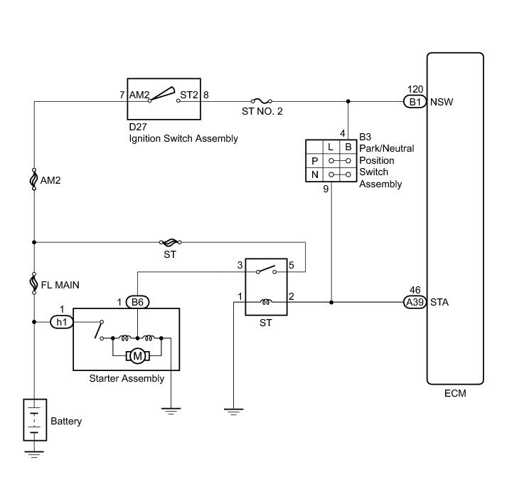
DESCRIPTION
While the engine is being cranked, current flows from terminal ST2 of the ignition switch to the park/neutral position switch and also flows to terminal STA of the ECM (STA signal).
WIRING DIAGRAM
INSPECTION PROCEDURE
NOTICE:
Inspect the fuses for circuits related to this system before performing the following inspection procedure.
PROCEDURE
1. READ VALUE USING TECHSTREAM (STARTER SIGNAL)
(a) Connect the Techstream to the DLC3.
(b) Turn the ignition switch to ON.
(c) Turn the Techstream on.
(d) Enter the following menus: Powertrain / Engine / Data List / Starter Signal.
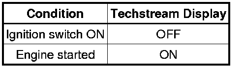
(e) Read the value displayed on the Techstream when the ignition switch is turned ON and the engine is started.
OK:
Result
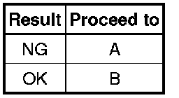
B -- CHECK HARNESS AND CONNECTOR (PARK/NEUTRAL POSITION SWITCH ASSEMBLY - ST RELAY - ECM)
A -- Continue to next step.
2. INSPECT PARK/NEUTRAL POSITION SWITCH ASSEMBLY (B - L)
(a) Inspect the park/neutral position switch assembly for 2WD, Component Tests and General Diagnostics for AWD).
Result
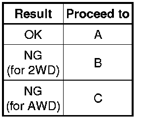
B -- REPLACE PARK/NEUTRAL POSITION SWITCH ASSEMBLY (FOR 2WD)
C -- REPLACE PARK/NEUTRAL POSITION SWITCH ASSEMBLY (FOR AWD) Removal
A -- Continue to next step.
3. INSPECT IGNITION SWITCH ASSEMBLY (AM2 - ST2)
(a) Inspect the ignition switch assembly Testing and Inspection.
NG -- REPLACE IGNITION SWITCH ASSEMBLY Removal
OK -- Continue to next step.
4. CHECK HARNESS AND CONNECTOR (IGNITION SWITCH ASSEMBLY - PARK/NEUTRAL POSITION SWITCH ASSEMBLY)
(a) Disconnect the ignition switch assembly connector.
(b) Disconnect the park/neutral position switch assembly connector.
(c) Measure the resistance according to the value(s) in the table below.
Standard Resistance (Check for Open):

Standard Resistance (Check for Short):

NG -- REPAIR OR REPLACE HARNESS OR CONNECTOR
OK -- Continue to next step.
5. CHECK HARNESS AND CONNECTOR (PARK/NEUTRAL POSITION SWITCH ASSEMBLY - ST RELAY - ECM)
(a) Remove the ST relay from the engine room relay block.
(b) Disconnect the park/neutral position switch assembly connector.
(c) Disconnect the ECM connector.
(d) Measure the resistance according to the value(s) in the table below.
Standard Resistance (Check for Open):

Standard Resistance (Check for Open):

NG -- REPAIR OR REPLACE HARNESS OR CONNECTOR
OK -- Continue to next step.
6. INSPECT BATTERY
(a) Check that the battery is not depleted.
OK:
Battery is not depleted.
NG -- REPLACE BATTERY
OK -- Continue to next step.
7. CHECK BATTERY TERMINAL
(a) Check that the battery terminal are not loose or corroded.
OK:
Battery terminals are not loose or corroded.
NG -- REPAIR OR REPLACE BATTERY TERMINAL
OK -- REPAIR OR REPLACE STARTER CIRCUIT (STARTER ASSEMBLY - ST RELAY)