Part 2
U760E AUTOMATIC TRANSMISSION / TRANSAXLE: AUTOMATIC TRANSAXLE UNIT: DISASSEMBLY (Continued..)
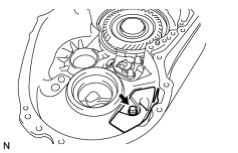
26. REMOVE DIFFERENTIAL DRIVE PINION TAPERED ROLLER BEARING RH (OUTER RACE)
(a) Using SST, remove the differential drive pinion tapered roller bearing RH (outer race) and shim from the transaxle housing.
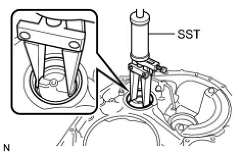
SST : 09308-00010
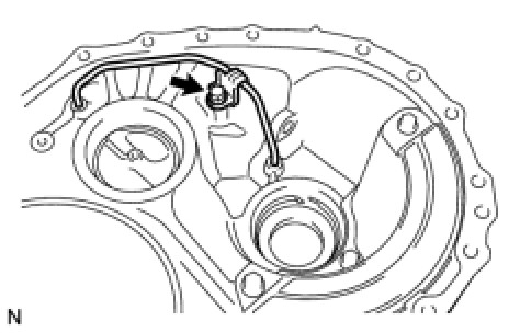
27. REMOVE DIFFERENTIAL GEAR LUBE APPLY TUBE
(a) Remove the bolt, clamp, and differential gear lube apply tube from the transaxle housing.
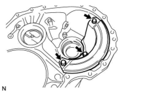
28. REMOVE TRANSAXLE HOUSING OIL SEPARATOR
(a) Remove the 3 bolts and transaxle housing oil separator from the transaxle housing.
29. REMOVE FRONT OIL PUMP ASSEMBLY
(a) Remove the O-ring from the front oil pump assembly.
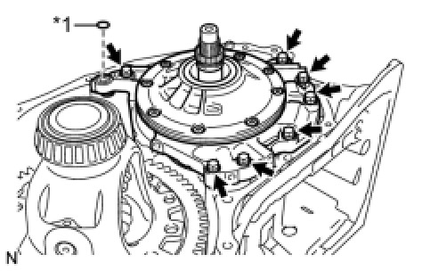
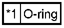
Text in Illustration
(b) Remove the 7 bolts and front oil pump assembly from the transaxle case.
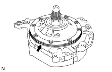
(c) Remove the O-ring from the front oil pump assembly.
(d) Remove the thrust needle roller bearing and thrust bearing race from the counter drive gear nut.
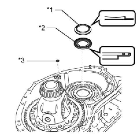
Text in Illustration
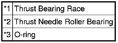
(e) Remove the O-ring from the transaxle case.
30. REMOVE NO. 3 BRAKE DISC
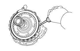
(a) Using a screwdriver, remove the snap ring from the front oil pump assembly.
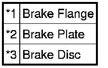
(b) Remove the 2 brake flanges, 3 brake discs, and 2 brake plates from the front oil pump assembly.
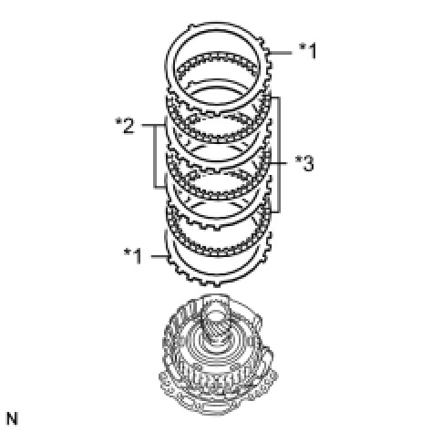
Text in Illustration
31. INSPECT NO. 3 BRAKE DISC Transaxle Unit
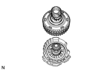
32. REMOVE UNDERDRIVE PLANETARY GEAR ASSEMBLY
(a) Remove the underdrive planetary gear assembly from the front oil pump assembly.
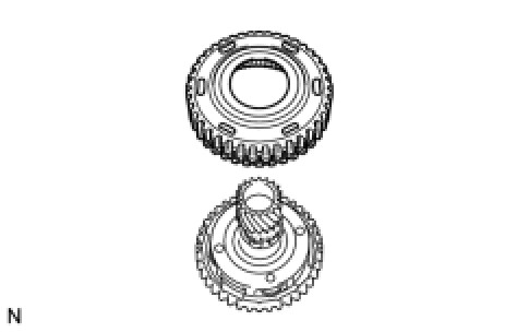
33. REMOVE NO. 3 BRAKE HUB
(a) Remove the No. 3 brake hub from the underdrive planetary gear assembly.
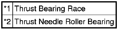
(b) Remove the thrust needle roller bearing and thrust bearing race from the underdrive planetary gear assembly.
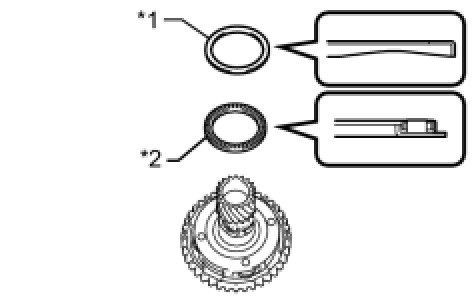
Text in Illustration
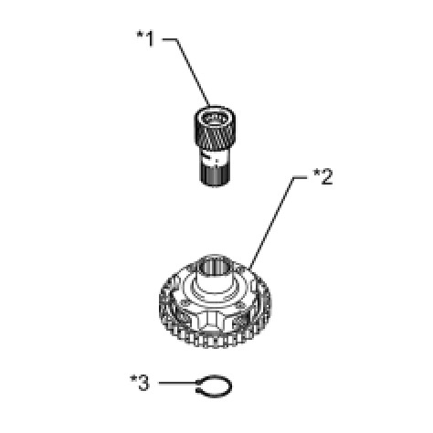
34. REMOVE PLANETARY SUN GEAR SUB-ASSEMBLY
(a) While expanding the snap ring with snap ring pliers, remove the planetary sun gear from the underdrive planetary gear assembly.
Text in Illustration
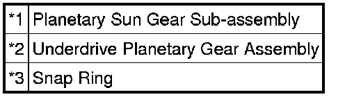
(b) Remove the snap ring from the underdrive planetary gear assembly.
35. INSPECT UNDERDRIVE PLANETARY GEAR ASSEMBLY Transaxle Unit
36. INSPECT PLANETARY SUN GEAR SUB-ASSEMBLY Transaxle Unit
37. REMOVE INPUT SHAFT SUB-ASSEMBLY
(a) Remove the input shaft sub-assembly from the front oil pump assembly.
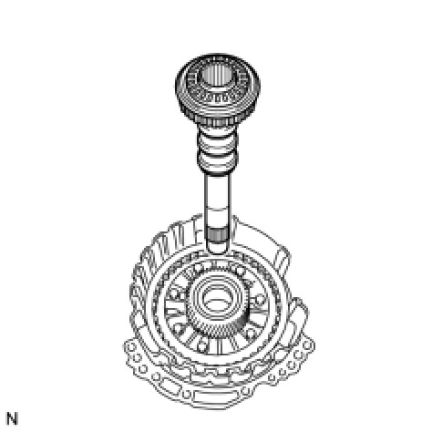
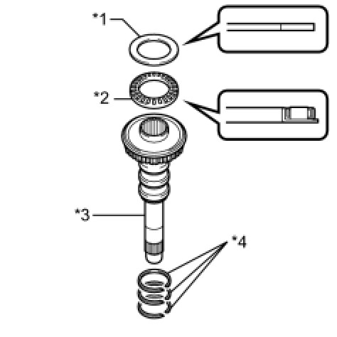
(b) Remove the thrust needle roller bearing and thrust bearing race from the input shaft sub-assembly.
Text in Illustration
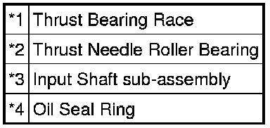
(c) Using a screwdriver, remove the 3 oil seal rings from the input shaft sub-assembly.
38. REMOVE UNDERDRIVE PLANETARY SUN GEAR
(a) Remove the underdrive planetary sun gear from the front oil pump assembly.
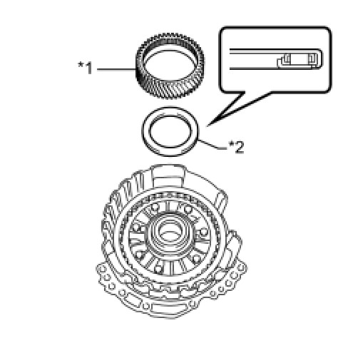
Text in Illustration
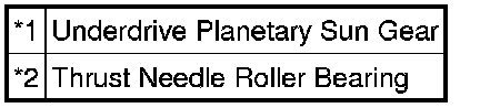
(b) Remove the thrust needle roller bearing from the front oil pump assembly.
39. REMOVE NO. 1 BRAKE DISC
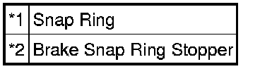
(a) Using a screwdriver, remove the 2 snap rings and brake snap ring stopper from the front oil pump assembly.
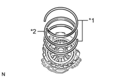
Text in Illustration
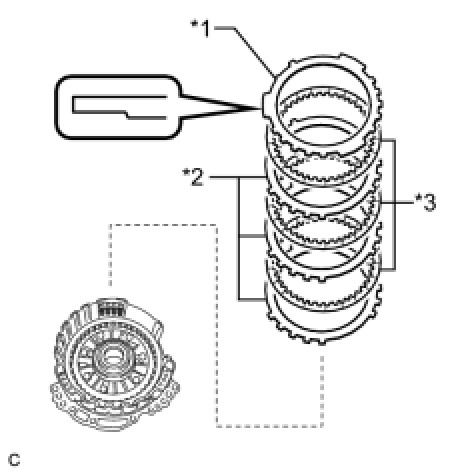
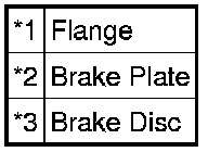
(b) Remove the flange, 3 brake discs, and 3 brake plates from the front oil pump assembly.
Text in Illustration
40. INSPECT NO. 1 BRAKE DISC Transaxle Unit
41. REMOVE 2ND BRAKE PISTON RETURN SPRING SUB-ASSEMBLY
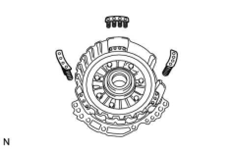
(a) Remove the 3 2nd brake piston return springs from the front oil pump assembly.
42. INSPECT 2ND BRAKE PISTON RETURN SPRING SUB-ASSEMBLY Transaxle Unit
43. REMOVE NO. 1 BRAKE PISTON
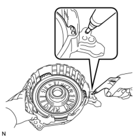
(a) Holding the front oil pump assembly by hand, apply compressed air (392 kPa, 4.0 kgf/cm2, 57 psi) to the front oil pump assembly to remove the No. 1 brake piston.
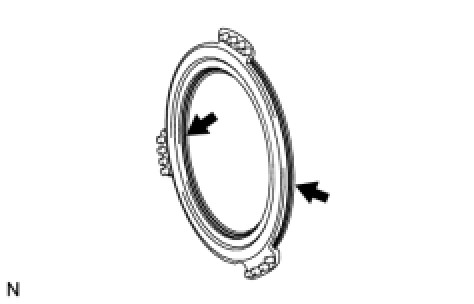
(b) Using a screwdriver, remove the 2 O-rings from the No. 1 brake piston.
44. REMOVE FRONT DIFFERENTIAL CASE
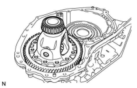
(a) Remove the front differential case from the transaxle case.
45. REMOVE COUNTER DRIVE GEAR NUT
(a) Using SST and a hammer, unstake the counter drive gear nut.
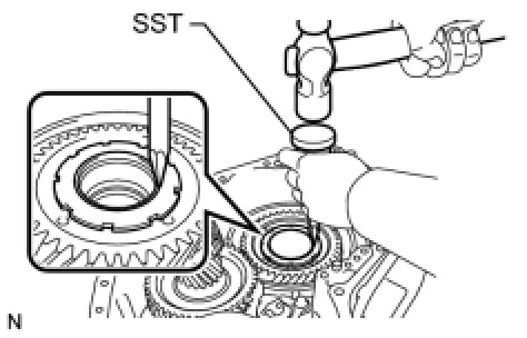
SST : 09930-00010
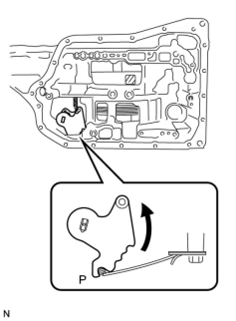
(b) Turn the manual valve lever shaft counterclockwise to set it to the P position as shown in the illustration.
(c) Using SST, remove the counter drive gear nut from the planetary gear assembly.
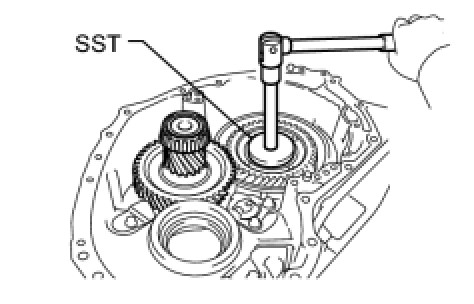
SST : 09387-00130
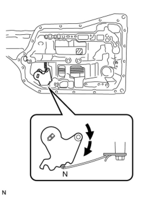
(d) Turn the manual valve lever shaft 2 notches clockwise to set it to the N position as shown in the illustration.
46. REMOVE COUNTER DRIVEN GEAR
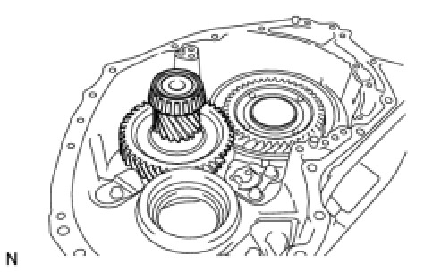
(a) Remove the counter driven gear from the transaxle case.
47. REMOVE DIFFERENTIAL DRIVE PINION TAPERED ROLLER BEARING RH (INNER RACE)
(a) Using SST, remove the differential drive pinion tapered roller bearing RH (inner race) from the counter driven gear.
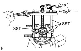
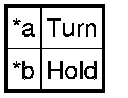
Text in Illustration
SST : 09950-00020
SST : 09950-00030
SST : 09950-40011
09957-04010
SST : 09950-60010
09951-00320
48. REMOVE DIFFERENTIAL DRIVE PINION TAPERED ROLLER BEARING LH (INNER RACE)
HINT
If removing the differential drive pinion tapered roller bearing LH (inner race), replace the counter driven gear with a new one.
49. REMOVE PAWL SHAFT CLAMP
(a) Remove the bolt and pawl shaft clamp from the transaxle case.
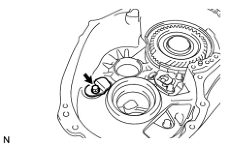
50. REMOVE NO. 1 TRANSMISSION CASE PLATE
(a) Remove the bolt and No. 1 transmission case plate from the transaxle case.