Part 2
U760E AUTOMATIC TRANSMISSION / TRANSAXLE: AUTOMATIC TRANSAXLE UNIT: REASSEMBLY (Continued..)
26. INSTALL NO. 1 BRAKE PISTON
(a) Coat 2 new O-rings with ATF and install them to the No. 1 brake piston.
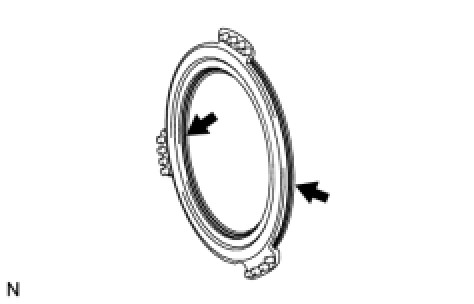
NOTICE:
Ensure that the 2 O-rings are not twisted.
(b) Install the No. 1 brake piston to the front oil pump assembly.
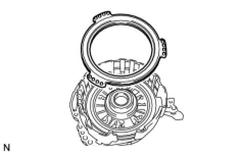
NOTICE:
Be careful not to damage the O-rings.
27. INSTALL 2ND BRAKE PISTON RETURN SPRING SUB-ASSEMBLY
(a) Install the 3 2nd brake piston return springs to the front oil pump assembly.
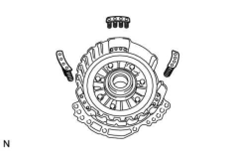
NOTICE:
Make sure that the 3 2nd brake piston return springs are installed onto the protrusions on the front oil pump assembly.
28. INSTALL NO. 1 BRAKE DISC
(a) Install the 3 brake discs, 3 brake plates, and brake flange to the front oil pump assembly.
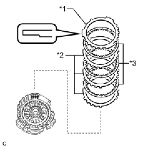
Text in Illustration
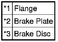
NOTICE:
* Make sure that the discs, plates, and flange are installed in the correct order.
* Be sure to install the flange in the correct direction.
(b) Place SST on the flange and compress the flange with a press.
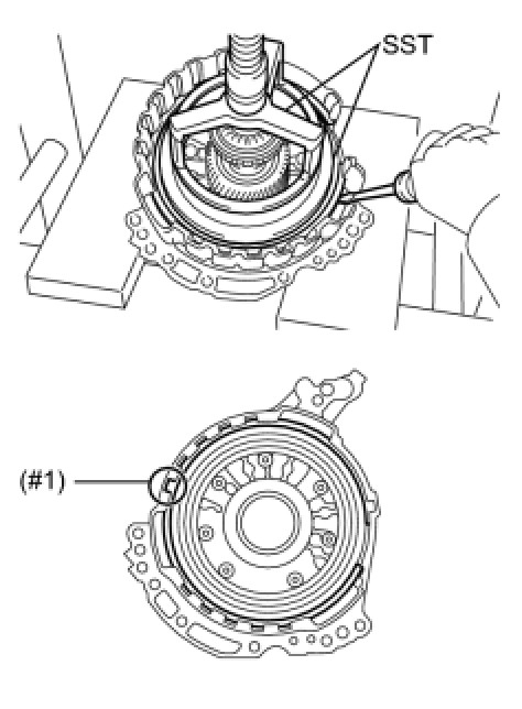
SST : 09387-00070
SST : 09495-65040
NOTICE:
Stop the press when the brake piston return spring is flush with the snap ring groove. This prevents the brake piston return spring from being deformed.
(c) Using a screwdriver, install the snap ring to the front oil pump assembly as shown in the illustration.
NOTICE:
* Confirm that the snap ring is correctly located in the groove of the oil pump.
* Make sure to align the protruding part of the snap ring with the indented part (#1) of the front oil pump and gear body assembly shown in the illustration to install the snap ring.
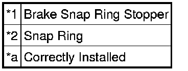
(d) Install the brake snap ring stopper to the front oil pump assembly.
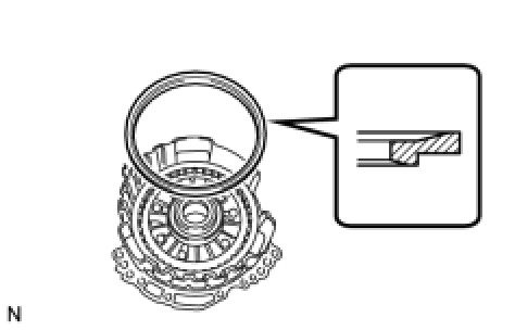
NOTICE:
Be sure to install the brake snap ring stopper in the correct direction.
(e) Using a screwdriver, install the snap ring to the front oil pump assembly as shown in the illustration.
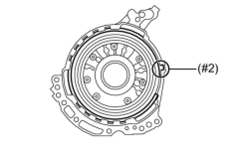
NOTICE:
* Confirm that the snap ring is correctly located in the groove of the oil pump.
* Make sure to align the protruding part of the snap ring with the indented part (#2) of the front oil pump assembly shown in the illustration to install the snap ring.
(f) Check that the brake snap ring stopper can be turned by hand.
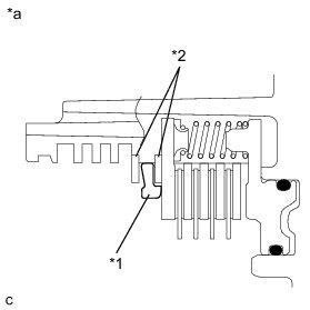
Text in Illustration
NOTICE:
If the brake snap ring stopper cannot be turned by hand, the brake snap ring stopper may have been installed upside down, or the snap ring may not have been completely located in the groove on the oil pump. Remove and reinstall the snap ring and the brake snap ring stopper.
29. INSPECT CLEARANCE OF NO. 1 BRAKE Transaxle Unit
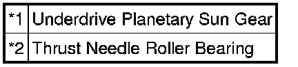
30. INSTALL UNDERDRIVE PLANETARY SUN GEAR
(a) Coat the thrust needle roller bearing with ATF, and install it to the front oil pump assembly.
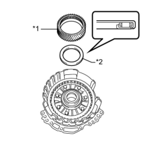
Text in Illustration
Bearing Diameter

NOTICE:
Be sure to install the thrust needle roller bearing properly so that the temper colored side of the race will be visible.
(b) Install the underdrive planetary sun gear to the front oil pump assembly.
31. INSTALL INPUT SHAFT SUB-ASSEMBLY
(a) Coat 3 new oil seal rings with ATF and install them to the input shaft sub-assembly.
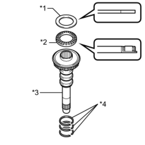
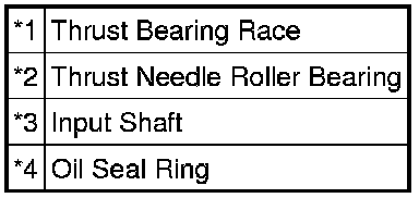
Text in Illustration
NOTICE:
Do not expand the gap of the oil seal ring too much.
(b) Coat the thrust needle roller bearing and thrust bearing race with ATF, and install them on the input shaft sub-assembly.
Bearing and Race Diameter
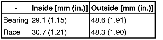
NOTICE:
Be sure to install the thrust needle roller bearing in the correct direction.
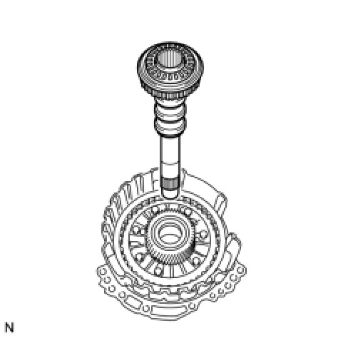
(c) Install the input shaft to the front oil pump assembly.
32. INSTALL PLANETARY SUN GEAR SUB-ASSEMBLY
(a) Using a snap ring expander, install the snap ring to the underdrive planetary gear assembly.
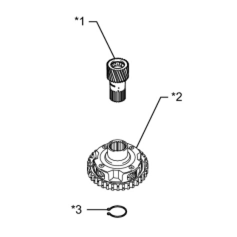
Text in Illustration
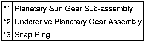
(b) Using a snap ring expander, install the planetary sun gear sub-assembly to the underdrive planetary gear assembly with the snap ring expanded.
33. INSTALL NO. 3 BRAKE HUB
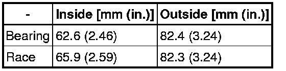
(a) Coat the thrust needle roller bearing with ATF and install it on the underdrive planetary gear assembly.
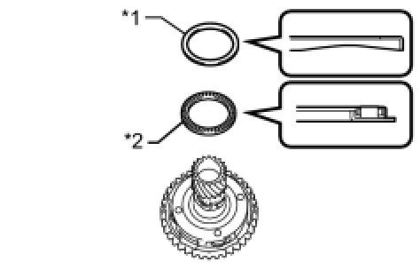
Text in Illustration
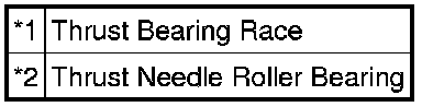
Bearing and Race Diameter
NOTICE:
Be sure to install the thrust needle roller bearing properly so that the temper colored side of the race will be visible.
(b) Coat the thrust bearing race with MP grease and install it to the No. 3 brake hub.
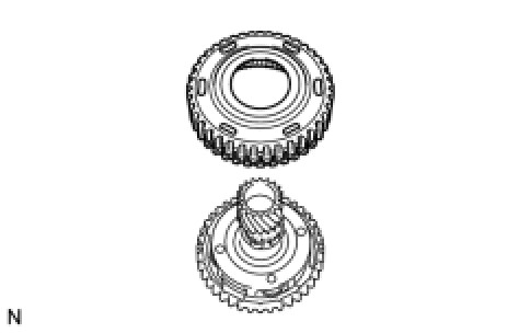
(c) Install the No. 3 brake hub to the underdrive planetary gear assembly.
34. INSTALL UNDERDRIVE PLANETARY GEAR ASSEMBLY
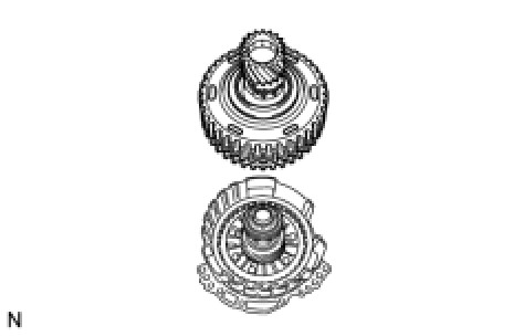
(a) Install the underdrive planetary gear assembly to the front oil pump assembly.
35. INSTALL NO. 3 BRAKE DISC
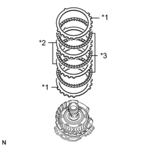
(a) Install the 2 brake flanges, 3 brake discs, and 2 brake plates to the front oil pump assembly.
Text in Illustration
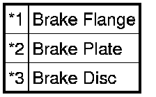
NOTICE:
Make sure that the discs, plates, and flanges are installed in the correct order.
(b) Using a screwdriver, install the snap ring to the front oil pump assembly.
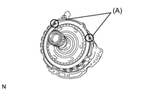
NOTICE:
* Confirm that the snap ring is correctly located in the groove of the oil pump.
* Make sure that the snap ring ends are positioned as shown in the illustration (A).
36. INSPECT CLEARANCE OF NO. 3 BRAKE Transaxle Unit
37. INSTALL FRONT OIL PUMP ASSEMBLY
(a) Coat a new O-ring with ATF and install it to the transaxle case.
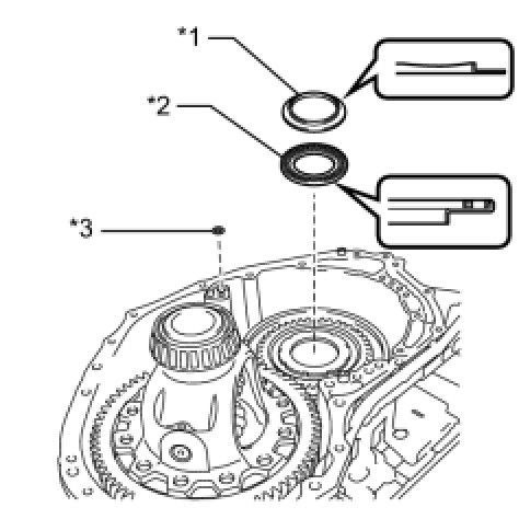
Text in Illustration
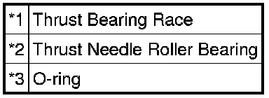
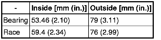
(b) Coat the thrust needle roller bearing and thrust bearing race with ATF and install them on the counter drive gear nut.
Bearing and Race Diameter
NOTICE:
Be sure to install the thrust needle roller bearing properly so that the temper colored side of the race will be visible.
(c) Coat a new O-ring with ATF and install it to the front oil pump assembly.
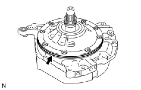
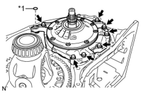
(d) Install the front oil pump assembly to the transaxle case with the 7 bolts.
Text in Illustration
Torque : 23 Nm (231 kgf-cm, 17 ft-lbf)
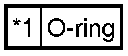
(e) Coat a new O-ring with ATF and install it to the front oil pump assembly.
38. INSTALL TRANSAXLE HOUSING OIL SEPARATOR
(a) Clean and degrease the 3 bolts and the installation holes in the transaxle housing.
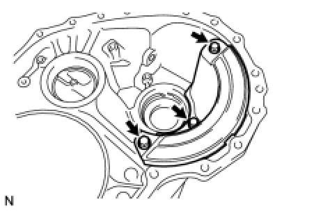
(b) Apply adhesive to 2 or 3 threads on the ends of the 3 bolts.
Adhesive:
Toyota Genuine Adhesive 1324, Three Bond 1324 or equivalent
(c) Install the transaxle housing oil separator to the transaxle housing with the 3 bolts.
Torque : 23 Nm (231 kgf-cm, 17 ft-lbf)
39. INSTALL DIFFERENTIAL GEAR LUBE APPLY TUBE
(a) Install the differential gear lube apply tube to the transaxle housing.
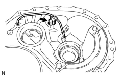
NOTICE:
Insert the differential gear lube apply tube into the transaxle housing until it makes contact with the stopper.
(b) Clean and degrease the bolt and the installation hole in the transaxle housing.
(c) Apply adhesive to 2 or 3 threads on the ends of the bolt.
Adhesive:
Toyota Genuine Adhesive 1324, Three Bond 1324 or equivalent
(d) Install the apply tube clamp to the differential gear lube apply tube with the bolt.
Torque : 23 Nm (231 kgf-cm, 17 ft-lbf)
NOTICE:
There should be clearance between the differential lube apply tube and apply tube clamp.
40. INSTALL DIFFERENTIAL DRIVE PINION TAPERED ROLLER BEARING RH (OUTER RACE)
(a) Install the shim to the transaxle housing.
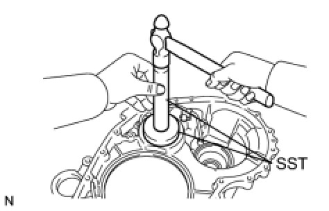
(b) Using SST, install a new differential drive pinion tapered roller bearing RH (outer race) to the transaxle housing.
SST : 09950-60020
09951-00710
SST : 09950-70010
09951-07100
NOTICE:
Be sure to install the differential drive pinion tapered roller bearing so that there is no clearance between the bearing outer race, shim and the transaxle housing. If there is any clearance, the turning torque of the counter drive gear cannot be measured correctly.
41. ADJUST COUNTER DRIVEN GEAR PRELOAD
(a) Remove packing material from the contact surfaces between the transaxle housing and case.
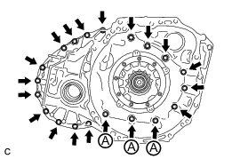
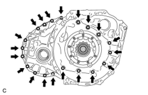
(b) Install the transaxle housing to the transaxle case with the 20 bolts.
Bolt A - Torque : 23 Nm (231 kgf-cm, 17 ft-lbf)
except Bolt A - Torque : 31 Nm (312 kgf-cm, 23 ft-lbf)
(c) Using SST and a torque wrench, measure the turning torque of the counter driven gear while rotating SST at 10 rpm.
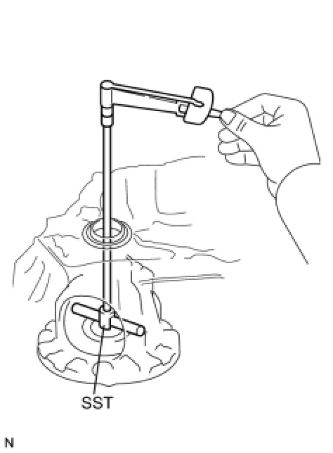
SST : 09564-33010
Turning torque:
Differential side bearing preload + 3.44 to 7.04 N*m (35.08 to 71.78 kgf*cm, 30.45 to 62.30 in.*lbf)
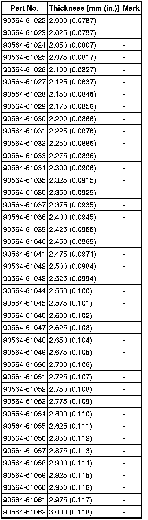
If the turning torque is not within the specified range, refer to the table below to select a shim of the counter driven gear front tapered roller bearing (outer race) so that the turning torque is within the specified range.
Shim Thickness
(d) Remove the 20 bolts and the transaxle housing.
42. INSTALL TRANSAXLE HOUSING
(a) Clean and degrease the contact surfaces between the transaxle housing and case.
NOTICE:
Make sure that there is no ATF on the contact surfaces.
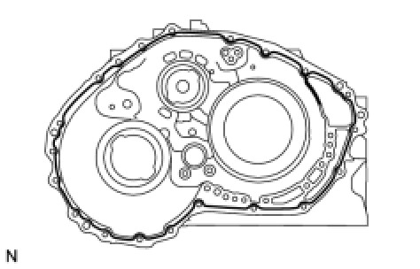
(b) Apply FIPG to the transaxle case.
FIPG:
Toyota Genuine Seal Packing 1281, Three Bond 1281 or equivalent
NOTICE:
* Apply FIPG in a continuous line (width 1.2 mm (0.0472 in.)) along the sealing surface.
* After applying FIPG, install the transaxle housing to the transaxle case within 3 minutes and tighten the bolts within 20 minutes.
(c) Install the transaxle housing to the transaxle case with the 17 bolts.
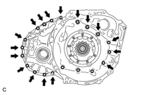
Torque : 31 Nm (312 kgf-cm, 23 ft-lbf)
(d) Clean and degrease the 3 bolts and the installation holes in the automatic transaxle.
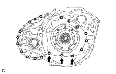
(e) Apply adhesive to 2 or 3 threads on the ends of the 3 bolts.
Adhesive:
Toyota Genuine Adhesive 1324, Three Bond 1324 or equivalent
(f) Install the 3 bolts.
Torque : 23 Nm (231 kgf-cm, 17 ft-lbf)
43. INSPECT CLEARANCE OF NO. 1 CLUTCH Transaxle Unit
44. INSTALL REAR PLANETARY SUN GEAR ASSEMBLY
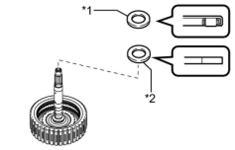
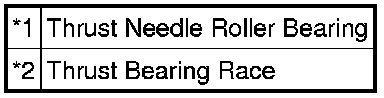
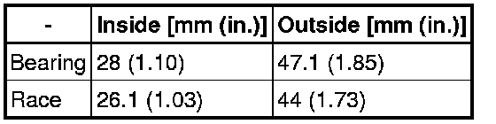
(a) Coat the thrust needle roller bearing and thrust bearing race with ATF, and install them to the direct multiple disc clutch assembly.
Text in Illustration
Bearing and Race Diameter
NOTICE:
Install the rear planetary sun gear thrust needle roller bearing properly so that the temper colored side of the race will be visible.
(b) Install the rear planetary sun gear assembly to the direct multiple disc clutch assembly.
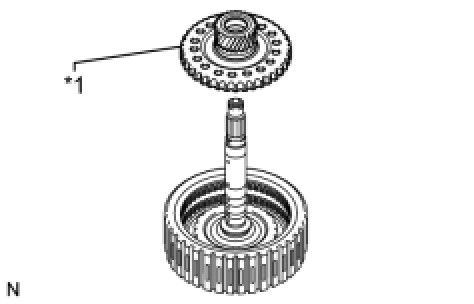
Text in Illustration

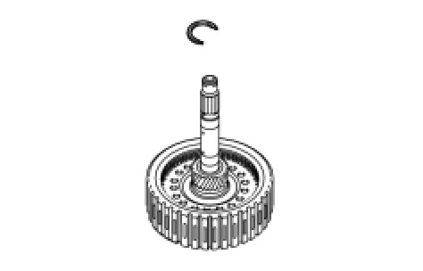
(c) Using a snap ring expander, install the snap ring to the direct multiple disc clutch assembly.
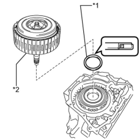
(d) Coat a new O-ring with ATF and install it to the direct multiple disc clutch assembly.
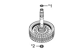
Text in Illustration
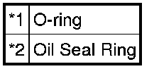
NOTICE:
Ensure that the O-ring is not twisted.
(e) Coat a new oil seal ring with ATF and install it to the intermediate shaft.
45. INSPECT CLEARANCE OF NO. 2 CLUTCH Transaxle Unit
46. INSTALL REAR MULTIPLE DISC CLUTCH ASSEMBLY
(a) Coat the rear thrust needle roller bearing with ATF and install it on the transaxle case.
Text in Illustration
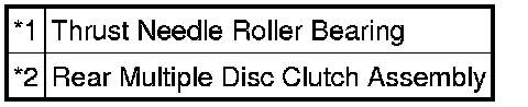
Bearing Diameter

(b) Install the direct multiple disc clutch assembly to the transaxle case.
47. INSPECT INTERMEDIATE SHAFT END PLAY Transaxle Unit
48. INSTALL REAR TRANSAXLE COVER SUB-ASSEMBLY
(a) Using SST and a hammer, install a new needle roller bearing into the rear transaxle cover sub-assembly.
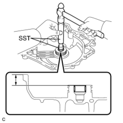
SST : 09950-60010
09951-00220
SST : 09950-70010
09951-07100
Installation depth:
21.5 to 21.9 mm (0.846 to 0862 in.)
(b) Clean and degrease the 2 "TORX" screws and the installation holes in the rear transaxle cover sub-assembly.
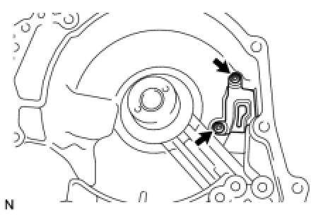
(c) Apply adhesive to 2 or 3 threads on the ends of the 2 "TORX" screws.
Adhesive:
Toyota Genuine Adhesive 1324, Three Bond 1324 or equivalent
(d) Using a T30 "TORX" socket wrench, install the rear transaxle cover plate to the rear transaxle cover sub-assembly with the 2 "TORX" screws.
Torque : 7.5 Nm (76 kgf-cm, 66 in-lbf)
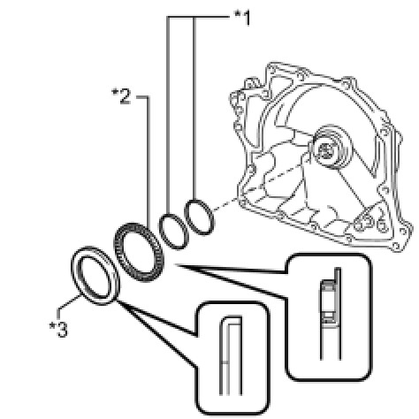
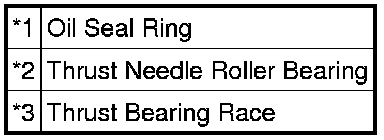
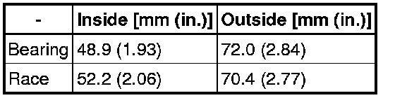
(e) Coat the thrust needle roller bearing and thrust bearing race with ATF and install them on the rear transaxle cover sub-assembly.
Text in Illustration
Bearing and Race Diameter
(f) Coat 2 new oil seal rings with ATF and install them to the rear transaxle cover sub-assembly.
(g) Coat 3 new O-rings with ATF and install them to the transaxle case.
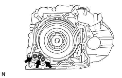
(h) Remove packing material from the contact surfaces between the rear transaxle cover sub-assembly and transaxle case.
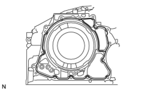
NOTICE:
Make sure that there is no ATF on the contact surfaces.
(i) Apply FIPG to the transaxle case.
FIPG:
Toyota Genuine Seal Packing 1281, Three Bond 1281 or equivalent.
NOTICE:
* Apply FIPG in a continuous line (width 1.2 mm (0.0472 in.)) along the sealing surface.
* After applying FIPG, install the rear transaxle cover sub-assembly to the transaxle case within 3 minutes and tighten the bolts within 20 minutes.
(j) Install the rear transaxle cover sub-assembly to the transaxle case with the 12 bolts.
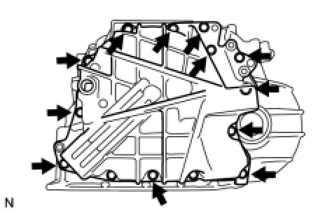
Torque : 23 Nm (231 kgf-cm, 17 ft-lbf)
(k) Clean and degrease the 2 bolts and the installation holes in the transaxle case.
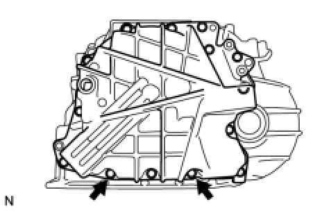
(l) Apply adhesive to 2 or 3 threads on the ends of the 2 bolts.
Adhesive:
Toyota Genuine Adhesive 1324, Three Bond 1324 or equivalent
(m) Install the 2 bolts.
Torque : 17 Nm (172 kgf-cm, 12 ft-lbf)
49. INSTALL REAR TRANSAXLE COVER PLUG
(a) Coat 3 new O-rings with ATF and install them to the 3 rear transaxle cover plugs.
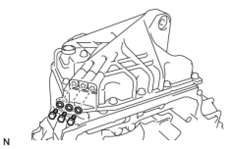
NOTICE:
Ensure that the 3 O-rings are not twisted.
(b) Install the 3 rear transaxle cover plugs to the rear transaxle cover sub-assembly.
Torque : 7.4 Nm (75 kgf-cm, 65 in-lbf)
50. INSTALL REFILL PLUG
(a) Install a new gasket to the refill plug.
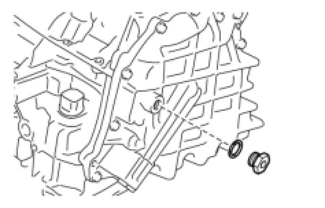
(b) Install the refill plug to the rear transaxle cover sub-assembly.
Torque : 49 Nm (500 kgf-cm, 36 ft-lbf)