Installation
FRONT SUSPENSION: FRONT SUSPENSION MEMBER (for Sedan): INSTALLATION
1. INSTALL ENGINE MOVING CONTROL ROD
(a) Install the engine moving control rod with the bolt.
Torque : 100 Nm (1020 kgf-cm, 74 ft-lbf)
HINT
Temporarily tighten the transaxle side, and then tighten the bolt to the specified torque.
2. INSTALL ENGINE MOVING CONTROL ROD COVER (for Cold Area)
(a) Install the engine moving control rod cover with the 2 clips.
3. TEMPORARILY TIGHTEN FRONT LOWER SUSPENSION ARM SUB-ASSEMBLY LH Installation
4. TEMPORARILY TIGHTEN FRONT LOWER SUSPENSION ARM SUB-ASSEMBLY RH
HINT
Use the same procedure for the RH side as for the LH side.
5. INSTALL FRONT STABILIZER BAR
6. INSTALL FRONT STABILIZER BRACKET LH Installation
7. INSTALL FRONT STABILIZER BRACKET RH
HINT
Use the same procedure for the RH side as for the LH side.
8. INSTALL STEERING GEAR ASSEMBLY Installation
9. INSTALL FRONT SUSPENSION CROSSMEMBER SUB-ASSEMBLY
(a) Place wooden blocks or plate lift attachments on an engine lifter, and then set the front suspension crossmember sub-assembly so that the attachments are in the positions shown in the illustration.
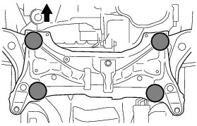
Text in Illustration
(b) Provisionally install the front suspension crossmember onto the body with the 6 bolts.
(c) By inserting SST into the datum holes in the front suspension crossmembers RH and LH alternately, tighten bolts A, B and C on both sides to the specified torque, in several steps.
SST : 09670-00011
Bolt A - Torque : 87 Nm (887 kgf-cm, 64 ft-lbf)
Bolt B - Torque : 151 Nm (1540 kgf-cm, 111 ft-lbf)
Bolt C - Torque : 98 Nm (999 kgf-cm, 72 ft-lbf)
NOTICE:
* Insert SST into the datum hole in a vertical orientation.
* If SST cannot be inserted into the datum hole vertically, loosen all the bolts and then insert SST again.
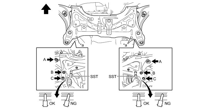
Text in Illustration
(d) Install the engine moving control rod with the bolt.
Torque : 120 Nm (1224 kgf-cm, 89 ft-lbf)
10. INSTALL FRONT LOWER SUSPENSION ARM SUB-ASSEMBLY LH
(a) Install the lower arm onto the steering knuckle with a new castle nut.
Torque : 98 Nm (999 kgf-cm, 72 ft-lbf)
NOTICE:
If the holes for the clip are not aligned, tighten the nut by a further turn of up to 60°.
(b) Install a new clip.
11. INSTALL FRONT LOWER SUSPENSION ARM SUB-ASSEMBLY RH
HINT
Use the same procedure for the RH side as for the LH side.
12. INSTALL TIE ROD END SUB-ASSEMBLY LH
(a) Install the tie rod end sub-assembly onto the steering knuckle with a new castle nut.
Torque : 49 Nm (500 kgf-cm, 36 ft-lbf)
NOTICE:
If the holes for the clip are not aligned, tighten the nut by a further turn of up to 60°.
(b) Install a new cotter pin.
13. INSTALL TIE ROD END SUB-ASSEMBLY RH
HINT
Use the same procedure for the RH side as for the LH side.
14. INSTALL FRONT STABILIZER LINK ASSEMBLY LH
(a) Install the front stabilizer link assembly with the nut.
Torque : 74 Nm (755 kgf-cm, 55 ft-lbf)
HINT
If the ball joint turns together with the nut, use a socket hexagon wrench 6 to hold the stud.
15. INSTALL FRONT STABILIZER LINK ASSEMBLY RH
HINT
Use the same procedure for the RH side as for the LH side.
16. INSTALL NO. 1 STEERING COLUMN HOLE COVER SUB-ASSEMBLY
(a) Install clip B onto the body portion and install the steering column hole cover onto the body portion with clip A.
NOTICE:
Make sure that the lip portion of steering column hole cover is not damaged.
17. INSTALL STEERING SLIDING YOKE SUB-ASSEMBLY
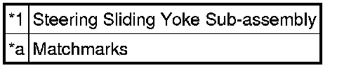
(a) Align the matchmarks and install the steering sliding yoke sub-assembly onto the power steering gear.
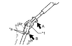
Text in Illustration
(b) Install the bolt B.
Torque : 35 Nm (360 kgf-cm, 26 ft-lbf)
(c) Tighten bolt A.
Torque : 35 Nm (360 kgf-cm, 26 ft-lbf)
18. INSTALL COLUMN HOLE COVER SILENCER SHEET
(a) Install the column hole cover silencer sheet with the 2 clips.
(b) Install the floor carpet.
19. INSTALL FRONT WHEEL
Torque : 103 Nm (1050 kgf-cm, 76 ft-lbf)
20. POSITION WHEELS FACING STRAIGHT AHEAD
21. STABILIZE SUSPENSION
(a) Lower the vehicle.
(b) Bounce the vehicle up and down several times to stabilize the suspension.
22. FULLY TIGHTEN FRONT LOWER SUSPENSION ARM SUB-ASSEMBLY LH
(a) Fully tighten the 2 bolts.
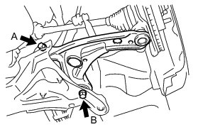
Bolt A - Torque : 137 Nm (1397 kgf-cm, 101 ft-lbf)
Bolt B - Torque : 151 Nm (1540 kgf-cm, 111 ft-lbf)
23. FULLY TIGHTEN FRONT LOWER SUSPENSION ARM SUB-ASSEMBLY RH
HINT
Use the same procedure for the RH side as for the LH side.
24. INSPECT AND ADJUST FRONT WHEEL ALIGNMENT
Front Wheel Alignment (for Sedan)
25. CHECK SPEED SENSOR SIGNAL
* w/o VSC Installation
* w/ VSC Installation