Accelerator Linkage/Cable Adjustment, Checking
Work sequence- depress accelerator pedal to full throttle position
^ throttle valve lever must contact stop, but kickdown lever on transmission must not be in kickdown position
- press accelerator pedal beyond full throttle to floor
^ override spring must be compressed and kickdown lever on transmission must be in kickdown position
If NO, adjust as follows:
Accelerator linkage/cable, adjusting
Work sequence
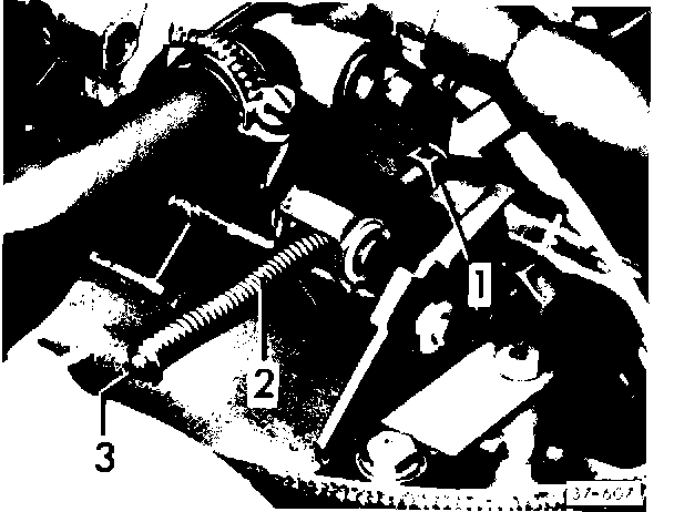
- loosen nut 1
- remove override spring 2
- start engine and run at idle
- check and adjust idle if necessary (see Repair Group 24)
- shut engine OFF
- pull accelerator rod in direction of arrow to stop (closed throttle position)
- turn adjusting rod 3 with screwdriver until shoulder of adjusting rod just contacts pivot of throttle lever
- reinstall override spring 2
- start engine and check idle speed
- if necessary, adjust idle speed by turning rod 3
- lock adjusting rod 3 in position with nut 1
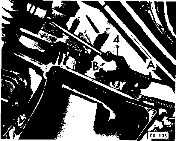
- press accelerator pedal to floor
^ kickdown lever 4 must be in kickdown position on stop (arrow A)
- release accelerator pedal
^ kickdown lever 4 must be in closed throttle position on stop (arrow B)
- if necessary, adjust accelerator cable at clamping bolt (arrow)
Wavy spring washer (See Vanagon 80-84 p. 38.7)
Wavy spring washer for 1st gear brake has been deleted. Apply shell has been lengthened as a result. 1st gear brake piston now has a ball valve.
FIGURE 1 - 1ST GEAR BRAKE PISTON, INSTALLING:
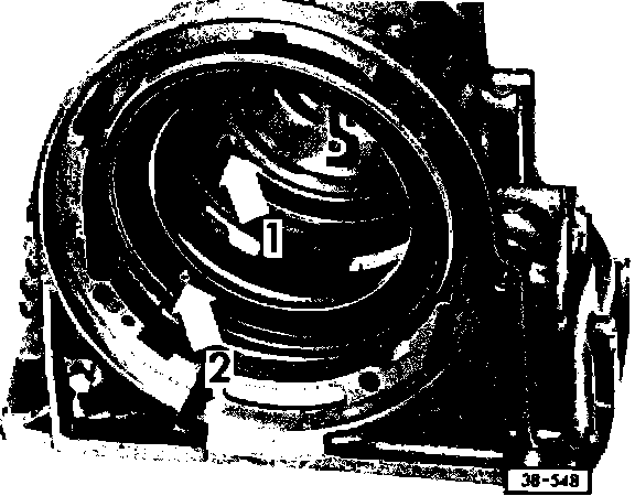
- lubricate with ATF
^ ball valve in piston (arrow 2) must line up with drilling in transmission housing (arrow 1)
FIGURE 2 - APPLY SHELL, INSTALLING:
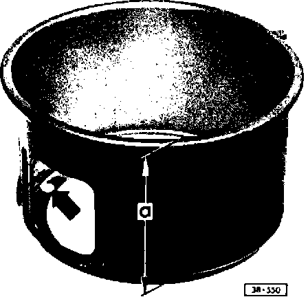
^ a = 97 mm
^ drilling (arrow) must line up with ball valve on 1st gear brake piston
Note
Number of inner and outer splined plates used with this length apply shell is 4 each.
New piston with ball valve and apply shell with drilling may be installed in previous transmissions with following requirements:
^ do not use wavy spring washer
^ only use 4 inner and 4 outer splined plates
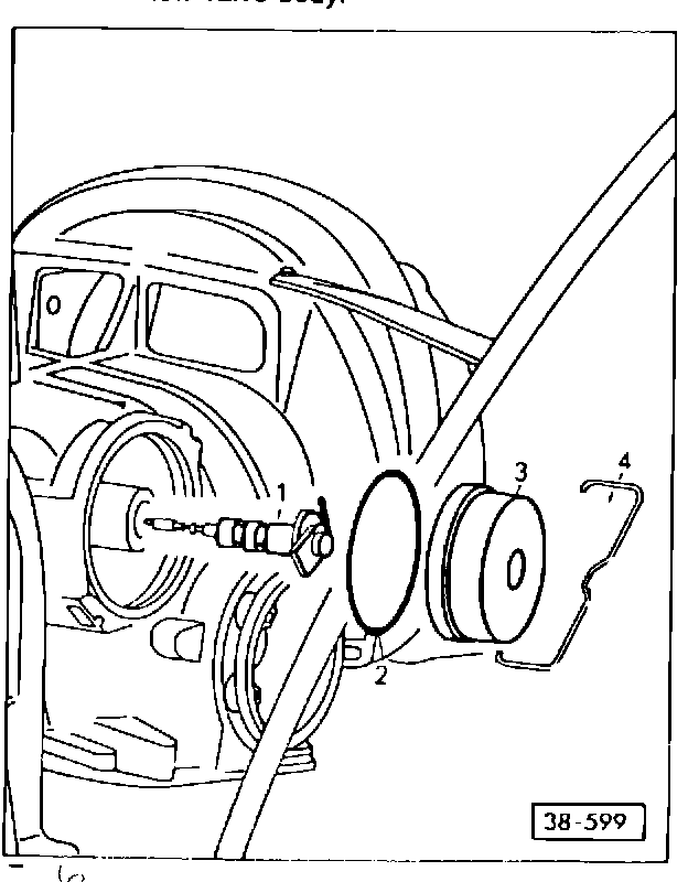
FIGURE 3 - ATF COOLER, INSTALLING:
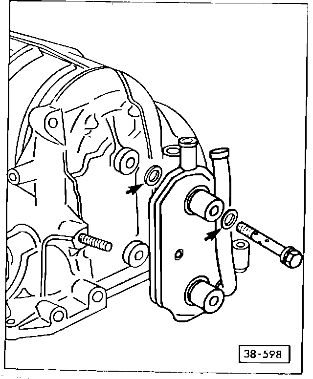
^ transmission is equipped with ATF cooler secured to transmission with union bolts and sealed with O-rings (arrows).
- tighten union bolts to 40 N-m (30 ft.lbs.)
Code letters (listed below) are stamped on governor head. New type governors are used only with new type valve bodies (see pages 7,8).
Transmission Valve Body Governor
Code Letters Code Letters Code Letters
NH FF A
Note
New governor may only be used with new type valve body. Previous type governor may also be used with new valve body.
FIGURE 4 - FLAT GOVERNOR:
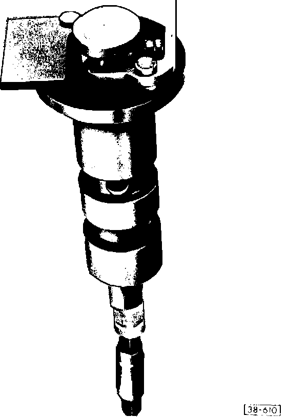
FIGURE 5 - GOVERNOR, IDENTIFICATION:
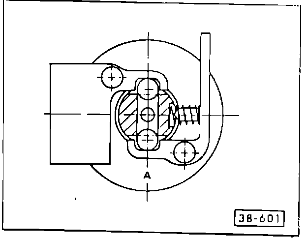
FIGURE 6 - GOVERNOR, REMOVING/INSTALLING:
1 - Flat governor 2 - O-ring
^ always replace 3 - Governor cap 4 - Clip
^ must be secure
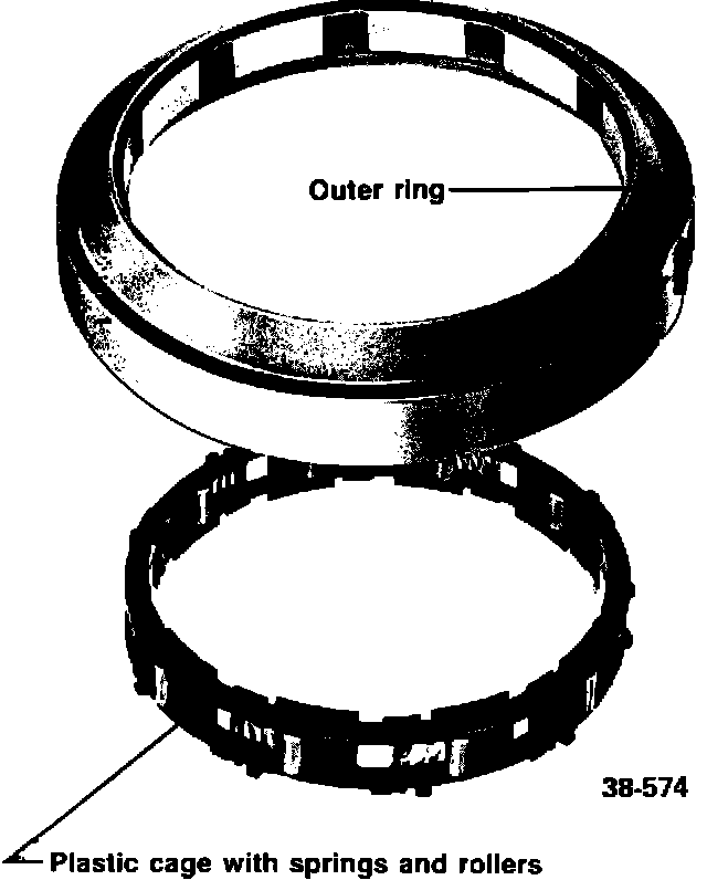
One-way clutch with plastic cage for rollers and springs
FIGURE 7 - PLASTIC CAGE SEGMENTS:
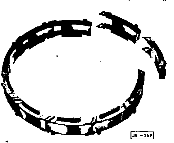
FIGURE 8 - SPRINGS AND ROLLERS, INSTALLING:
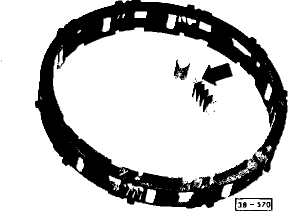
FIGURE 9 - INSTALLATION POSITION OF CAGE:
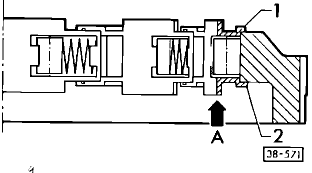
FIGURE 10 - SECURING CAGE:
assembling segments Fig. 7
installing springs and rollers Fig. 8
installation position of cage Fig. 9
securing cage Fig. 10
Note
New plastic cage can be service-installed in earlier transmissions. Circlips previously used have been discontinued and cannot be used with plastic cage.
FIGURE 7 - PLASTIC CAGE SEGMENTS:
- assemble 10 segments to form a ring
FIGURE 8 - SPRINGS AND ROLLERS, INSTALLING:
^ spring tab (arrow) toward roller
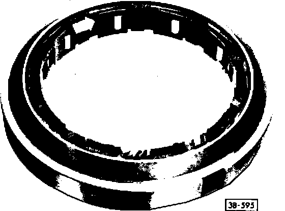
FIGURE 9 - INSTALLATION POSITION OF CAGE:
- insert cage into outer ring from below (direction of arrow A)
^ small ledge (1) at top
^ large ledge (2) at bottom
FIGURE 10 - SECURING CAGE:
- turn in direction of arrow