Ignition Coil: Testing and Inspection
Ignition coil (N 152), checking- perform following checks using Fluke 83 multimeter (US 1119)
- specified values are valid when measured at a temperature between 0 and 40°C (32 and 104°F)
If measured values deviate from specified values
- check for open or short circuits using proper wiring diagram before replacing components
- use the VW 1594 adaptor kit to make connections between the multimeter and the harness connectors
CAUTION: Switch the multimeter to the appropriate measuring range before making test connections.
- disconnect coil wire and power output stage harness connector from coil
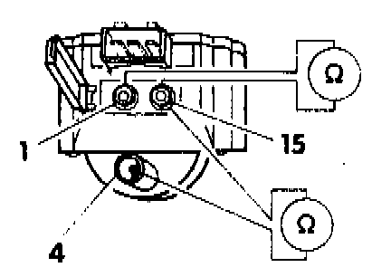
- check primary resistance between terminals 1 and 15
- must be 0.5 to 0.7 Ohms
-- check secondary resistance between terminals 4 and 15
- must be 3000 to 4000 Ohms
If specified values not obtained
- remove ignition coil and disconnect power output stage of ignition coil
- repeat check
If specifications still not obtained
- replace ignition coil (N 152)
Power output stage, checking
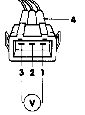
- switch multimeter to 20 Volt range
- connect multimeter between terminals 1 and 3 of disconnected power output stage harness connector 4
- switch ON ignition
- must be approx. battery voltage
If NO
- check for open or short circuit in harness wiring using wiring diagram, repair or replace as necessary
- switch OFF ignition
- disconnect multimeter
- disconnect fuel injector main harness connector or remove fuse 18
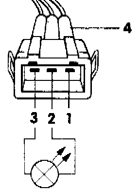
- connect US 1115 LED tester between terminals 2 and 3 of disconnected fuel injector harness connector 4 using jumper leads from VW 1594 adaptor kit
- operate starter to check signal from the Hall sender and the ignition switching function of the control unit
- LED tester must flicker
If NO
- check Hall sender (G 40), Testing and Inspection
If Hall sender OK
- replace Digifant control unit (J 169)
- reconnect fuel injector main harness connector or reinstall fuse 18
- reconnect ignition coil wire and power output stage harness connector
- switch OFF ignition
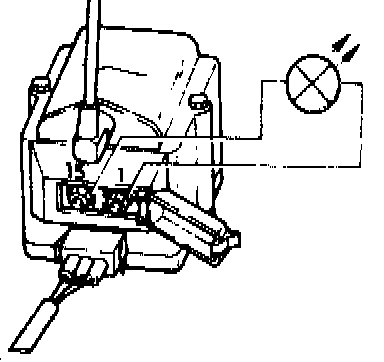
- connect multimeter between terminals 1 and 15 of ignition coil
CAUTION: Do not handle or cause the test connections to become disconnected during the following step.
- switch ON ignition
- must be 2 Volts minimum and then drop to 0 Volts after 1 to 2 seconds
- operate starter
- LED tester must flicker
If NO
- replace ignition coil with power output stage (N 157)