Oxygen Sensor Heating After Catalyst Checking
Oxygen sensor heating (for Oxygen sensor after Three Way Catalyst), checking
Special tools, testers, measuring instruments and auxiliary items required
- VAG 1551/1552 Scan Tool with VAG 1551/3B adaptor cable
- VAG 1598/22 Test Box
- Fluke 83 Multimeter
- VW 1594 Adaptor kit
- Wiring diagram
Check conditions
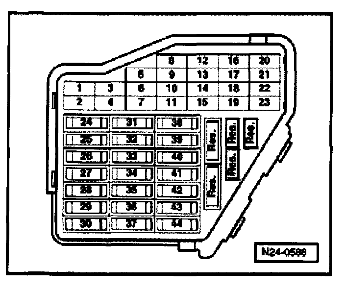
- Fuse 29 must be OK.
- Battery Voltage 11.5 Volts minimum
- Fuel pump relay must be OK
Test sequence
- Connect VAG 1551/1552 Scan Tool, [1][2][3]Reading and Clearing Diagnostic Trouble Codes
- Start engine and let idle
- Press 0 and 1 buttons to select "Address word" 01 "Engine electronics"
Display will appear as shown
Rapid data transfer HELP
Select function XX
- Press 0 and 8 buttons to select Function 08: "Read measuring value block"
- Press Q button to enter input
Display will appear as shown
Read measuring value block HELP
Input Display group number XXX
- Press 0, 4 and 1 buttons to select "Display group 41"
- Press Q button to enter input
Display will appear as shown (1 to 4 = Display zones)
Read measuring value block 41 ->
1 2 3 4
- Check specifications in Display zones 3 and 4.
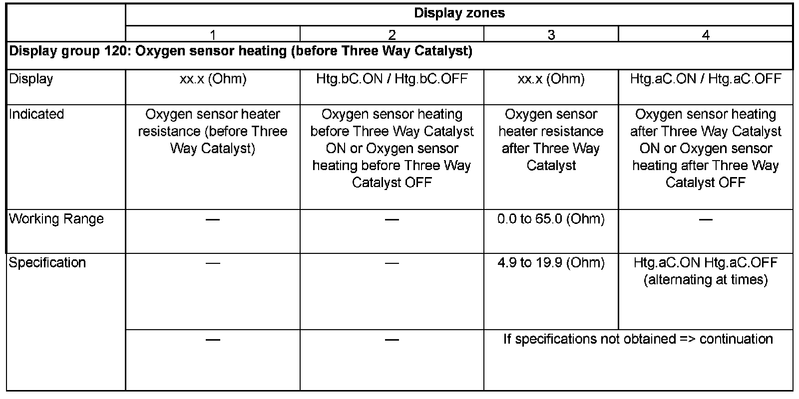
If specification obtained
- Press -> button.
- Press 0 and 6 buttons to select Function 06 "End data transfer"
- Press Q button to enter input
- Switch OFF ignition.
Continuation
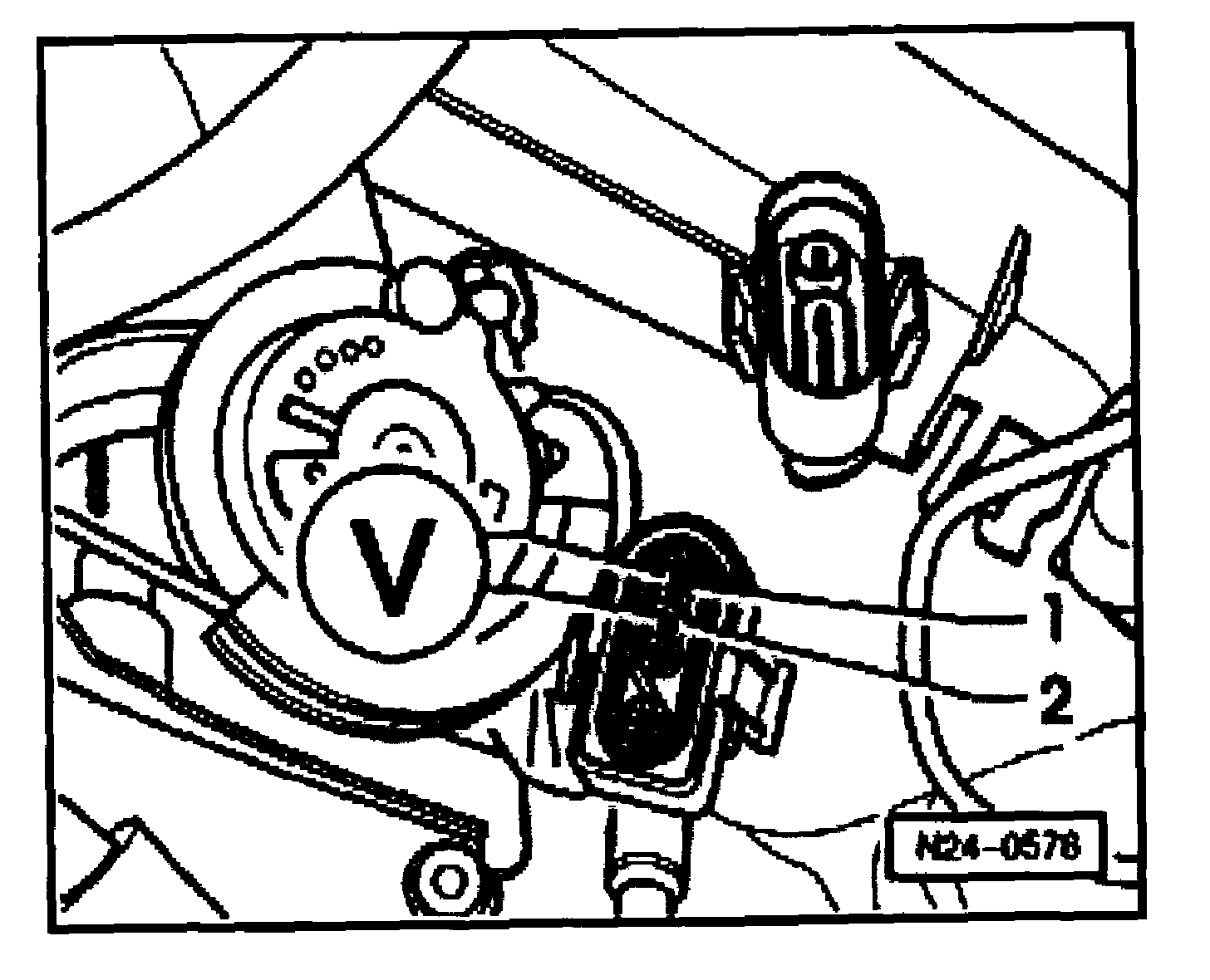
- Disconnect 4-pin harness connector (black) to Oxygen sensor -1- G108 (after Three Way Catalyst).
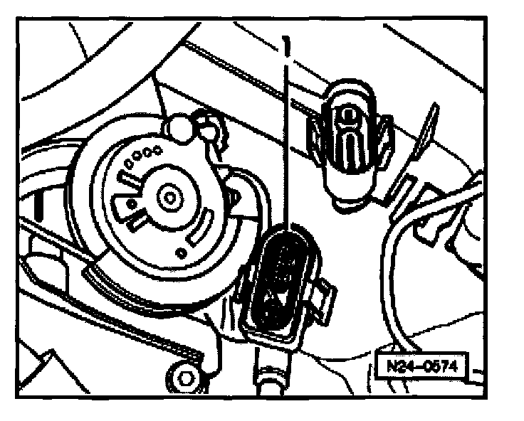
- Switch Multimeter to "Resistance" range
- Connect Multimeter between terminals 1 + 2 of Oxygen sensor connector using jumper wires from VW 1594 adaptor kit.
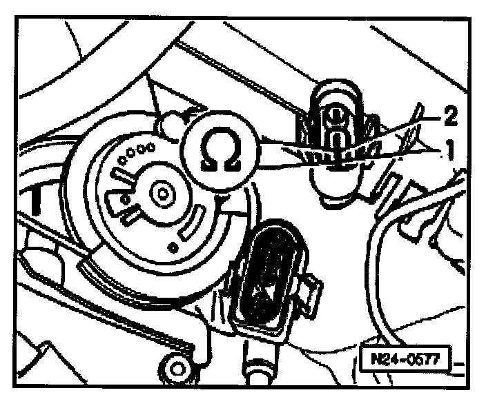
- Measure resistance.
- Specification: 0.0 to 19.9 Ohms
If specification obtained
- Set Multimeter to "Voltage measurement" range.
- Connect Multimeter using aux. cables from VW 1594 to measure Voltage at terminals 1 + 2 (connector to Engine Control Module).
- Start engine and let idle.
- Measure the Voltage supply:
When Display group 41, Display zone 4 shows
Display, Htg.aC.ON:
Specification: 11.0 to 14.5 Volts
Display, Htg. aC.ON/Htg.aC.OFF (alternating)
Specification: Between 0.0 and 12.0 Volts, fluctuating
- Switch OFF ignition.
If NO Voltage present:
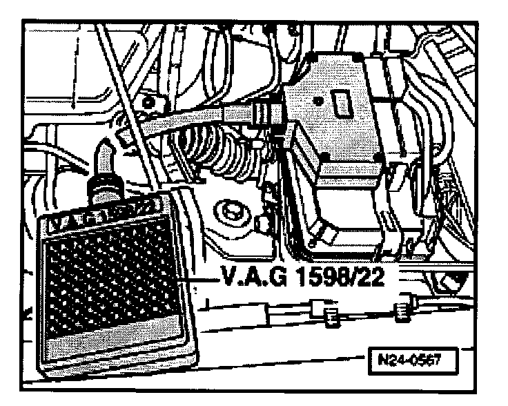
- Connect VAG 1598/22 Test Box to Control Module harness connector.
- Check wiring for open circuit between Test Box and 4-pin harness connector using Wiring diagram.
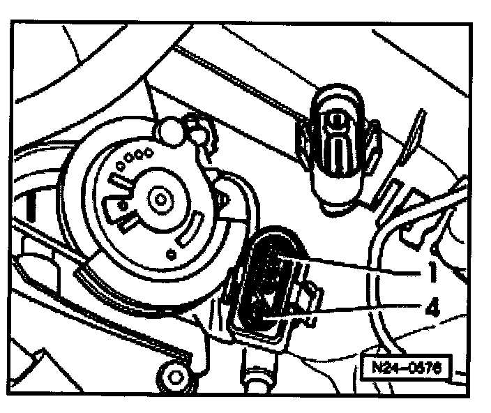
Terminal 2 + socket 28
Wire resistance: Max. 1.5 Ohms
If specification obtained
- Check wiring between terminal 1 and fuel pump relay J17 using Wiring diagram.
If wiring OK
- Replace engine electronics Control Module.
- Display Readiness Code, Monitors, Trips, Drive Cycles and Readiness Codes
NOTE: If DTC memory has been erased or the Engine Control Module was disconnected from its Voltage supply, the Readiness Code must be created again , Monitors, Trips, Drive Cycles and Readiness Codes