Body Side Overview
Cooling system components
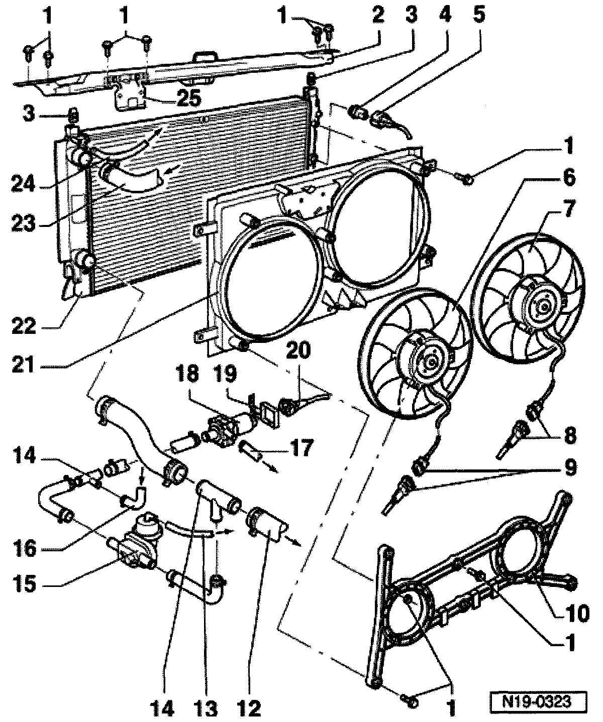
1 Bolt: Tighten to 10 Nm
2. Lock carrier
3. Securing rubber
4. Coolant Fan Control (FC) thermal switch -F18-, 35 Nm
- Switching temperatures,
1. Stage
On: 84 to 89 ° C
Off: 76 to 83 ° C
2. Stage
On: 90 to 95 ° C
Off: 82 to 89 ° C
5 Connector
- black, 3 pin
- for Coolant Fan Control (FC) thermal switch
6. Coolant fan -V7-
7. Right coolant fan -V35-
8. 2-way connector
- Black
- for right coolant fan -V35-
9. 2-way connector
- Black
- for coolant fan -V7-
10. Fan ring
11 Wire routing
12 Lower coolant hose
13 Vacuum hose
- to brake booster vacuum line
14 T connector
15 vacuum valve
- Vacuum valve must be closed when the engine is running.
- Arrow on vacuum valve points toward after-run coolant pump
16. Coolant hose
17. Coolant hose
18. After run coolant pump -V51-
19. Bracket
- for after run coolant pump
20. Connector
- black, 2-pin
- for after run coolant pump
21. Intake air elbow
22. Radiator
- After replacing, completely replace coolant
23 Upper coolant hose
24. Coolant overflow hose
25 Bracket for expansion tank
- secured to lock carrier