Fuel Pressure Regulator Valve, Checking
Fuel Pressure Regulator Valve, Checking
Recommended special tools and equipment
- V.A.G 1526 multimeter or V.A.G 1715 multimeter
- V.A.G 1594 connector test kit
- Wiring diagram
Test requirements
- Corresponding fuses on E-box in engine compartment, left side, for Fuel Pressure Regulator Valve -N276- must be OK.
NOTE: Fuses on this fuse holder are labelled "SB" in the wiring diagram.
- Ground (GND) connections between engine and chassis must be OK.
- For vehicles with automatic transmission, selector lever must be in -P-.
- Coolant temperature must be at least 80 degrees C, Diagnostic mode 1: Check measured values; PID 5 ($5), Coolant temperature.
- Ignition switched off.
Function test
Observe safety precautions.
Observe rules for cleanliness.
- Connect diagnostic tester.
- Start engine and let run at idle.
- Under address word 33, select "Diagnostic mode 1: Check measured values."
- Select the measuring value "PID 35 ($23): Fuel pressure (rail pressure)".
- Check specified value of fuel pressure (rail pressure) at idle:
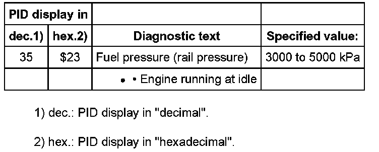
- End diagnosis and switch ignition off.
If specified value is not obtained:
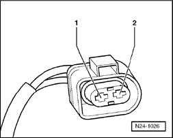
- Disconnect 2-pin connector from Fuel Pressure Regulator Valve -N276- at high pressure pump.
Checking resistance
- Check resistance between valve terminals.
Specified value: 1.0...5.0 ohms
If specified value is not obtained:
- Replace high pressure pump with Fuel Pressure Regulator Valve -N276-.
- Erase DTC memory of Engine Control Module (ECM), Diagnostic mode 4: Reset/erase diagnostic data. Diagnostic Mode 04 - Erase DTC Memory
- Generate readiness code. Monitors, Trips, Drive Cycles and Readiness Codes
If specified value is obtained:
- Check wires to Engine Control Module (ECM) according to wiring diagram.
Checking wires to Engine Control Module (ECM)
- Connect test box to 60-pin connector of wiring harness, connecting test box for wiring test. Test Box, Connecting For Wiring Test
Engine Control Module (ECM) is not connected.
- Check wire between test box and 2-pin connector to Engine Control Module (ECM) for open circuit according to wiring diagram.
Terminal 2 + socket 19
Wire resistance: max. 3.0 ohms
- Also check the wire for short circuit to B+ and to Ground (GND).
Specified value: infinity ohms
- Check wire between 2-pin connector terminal 1 and fuse holder for open circuit according to wiring diagram.
Wire resistance: max. 3.0 ohms
- Erase DTC memory of Engine Control Module (ECM), Diagnostic mode 4: Reset/erase diagnostic data. Diagnostic Mode 04 - Erase DTC Memory
- Generate readiness code. Monitors, Trips, Drive Cycles and Readiness Codes
If no malfunctions are found in wires:
- Replace Engine Control Module (ECM) -J623-