Knock Sensor: Service and Repair
Knock Sensor
• In the process for removing and installing the knock sensors, the fuel line must be opened. Observe the safety precautions. Refer to --> [ Safety Precautions ] Safety Precautions.
CAUTION!
The fuel injection system is divided into a high pressure side (maximum approximately 120 bar) and a low pressure side (approximately 6 bar).
Before opening high pressure side, e.g. removing high pressure pump, fuel rail, fuel injectors, fuel pipe or fuel metering valve (N290) or fuel metering valve 2 (N402), fuel pressure in high pressure side must be reduced to a residual pressure of 6 bar. The procedure for this is as follows. Refer to --> [ Releasing Pressure on High Pressure Side ] Service and Repair.
Removing
- Remove intake manifold:
Vehicles with aluminum intake manifolds, refer to --> [ Intake Manifold ] Intake Manifold.
Vehicles with plastic intake manifolds, refer to --> [ Intake Manifold ] Intake Manifold.
- Then, according to need, remove Knock Sensor (KS) 1 (G61) - 2 - or KS 2 (G66) - 9 -.
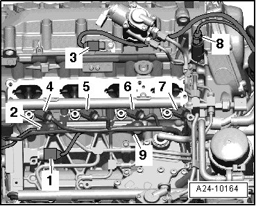
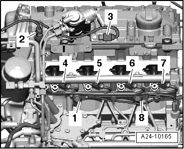
- Remove KS 3 (G198) - 8 - or KS 4 (G199) - 1 -.
Installing
- Attach the respective removed knock sensor in its installation location.
• Tightening specifications affects function of KS.
- Install the intake manifold.
Vehicles with aluminum intake manifolds, refer to --> [ Intake Manifold ] Intake Manifold.
Vehicles with plastic intake manifolds, refer to --> [ Intake Manifold ] Intake Manifold.
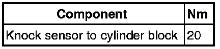
Tightening Specifications