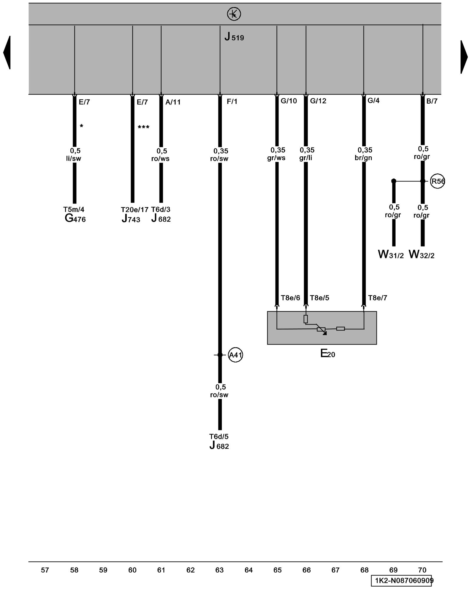
Diagram 87/6 (Tracks 57-70)
IMPORTANT NOTE:
This manufacturer uses "Track" style wiring diagrams.
For information on how to use these diagrams effectively, please refer to Diagram Information and Instructions. Diagram Information and Instructions
Instrument Panel Illumination Dimmer Switch, Vehicle Electrical System Control Module
ws = white
sw = black
ro = red
br = brown
gn = green
bl = blue
gr = grey
li = lilac
ge = yellow
or = orange
rs = pink
E20 - Instrument Panel Illumination Dimmer Switch
G476 - Clutch Position Sensor
J519 - Vehicle Electrical System Control Module Component Locations Vehicle Electrical System Control Module -J519-
J682 - Power Supply Relay (terminal 50) Locations
J743 - Direct Shift Gearbox (DSG) Mechatronic
T6d - 6-Pin Connector
T5m - 5-Pin Connector
T8e - 8-Pin Connector
T20e - 20-Pin Connector
W31 - Left Front Entry Light
W32 - Right Front Entry Light
(A41) - Plus Connection (50) (in instrument panel wiring harness)
(R56) - Courtesy Light Connection (in driver's door wiring harness)
* - Vehicle with Manual Transmission, only
*** - Vehicles with Direct Shift Automatic Transmission (DSG) 02E, only
Previous Diagram 87/5 (Tracks 43-56)
Next Diagram 87/7 (Tracks 71-84)