CIS Fuel Injection System
Fig. 244 DISCONNECT PULSAIR:
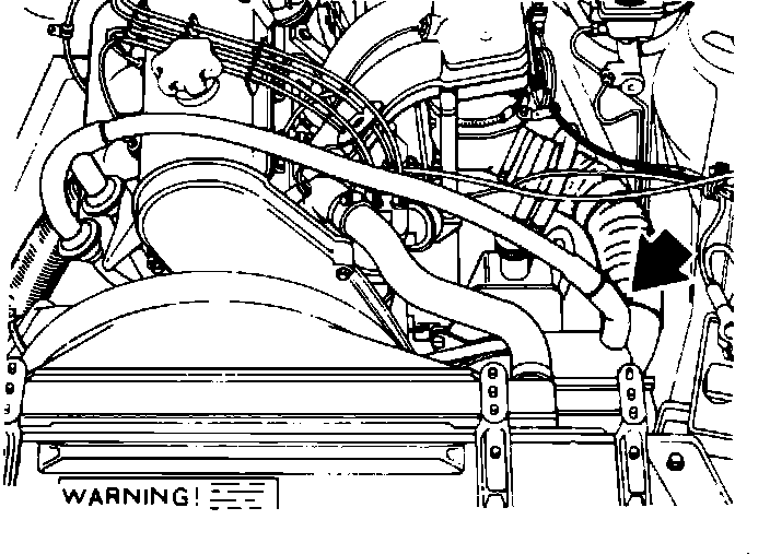
1. Connect CO meter.
Fig. 245 DISCONNECT E.G.R. SYSTEM:
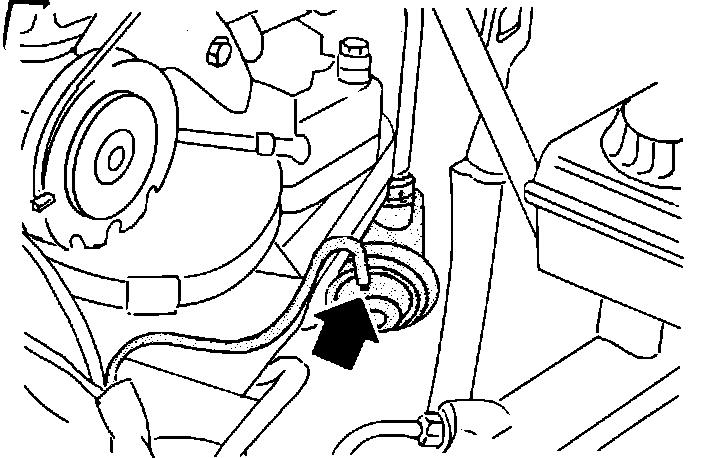
2. Disconnect E.G.R. valve and plug vacuum line (if equipped). Fig. 245.
Fig. 246 IDLE SPEED ADJUSTMENT:
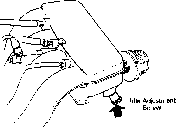
3. Run engine to normal operating temperature.
4. Check and adjust idle speed (900 ± 50 RPM). Fig. 246.
5. Check CO content. Value range is 0.5 - 2.0%.
6. Adjust CO only if it is out of value range.
7. CO. Adjustment hole may be sealed with a metal plug, if so proceed to following step. If seal has already been removed proceed to step 17 below.
8. To adjust CO, disconnect battery negative terminal.
Fig. 254 DISCONNECT FUEL LINES AT AIR-FUEL CONTROL UNIT:
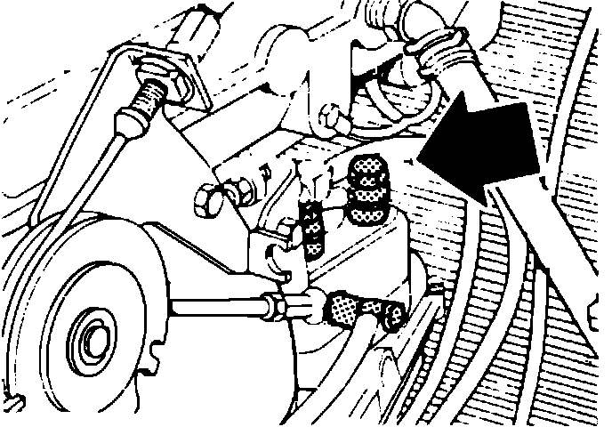
9. Disconnect all fuel lines at air-fuel control unit. Fig. 254.
Fig. 255 DISCONNECT RUBBER MOUNTS:
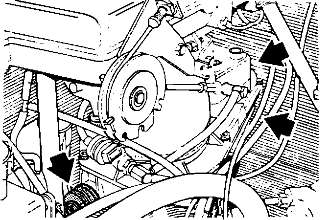
10. Disconnect rubber suspension mounts for air-fuel control unit.
11. Remove air-fuel control unit. Fig. 255.
Fig. 256 SEPERATE AIR-FUEL CONTROL UNIT:
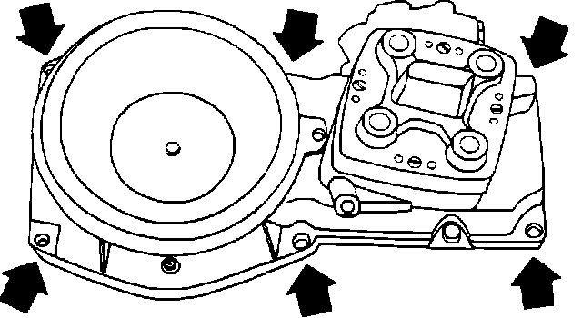
12. Separate air-fuel control unit by removing the screws retaining upper and lower part. Fig. 256.
Fig. 324 REMOVE CO ADJUSTMENT SEAL:
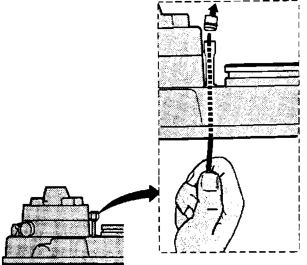
13. Metal plug can now be pushed out with a steel wire. Fig. 324.
14. Reassemble the air-fuel control unit. Install it in engine compartment and reconnect all fuel lines.
15. Reconnect battery negative cable.
16. Run engine to operating temperature.
Fig. 247 CO ADJUSTMENT:
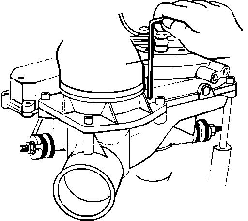
17. Set CO to 1.0% with VOLVO tool #5015 or equivalent (a long 3mm allen wrench will work). Fig. 247. Cover hole between adjustments while measuring CO content.
Fig. 325 INSTALL CO ADJUSTMENT SEAL:
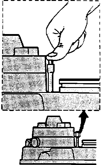
18. After adjustment, reinsert metal plug. Press it in with finger pressure. Fig. 325.
19. Reconnect E.G.R. valve (if equipped).
20. Recheck and adjust idle speed (900 ± 50 RPM) if necessary
21. Disconnect all test equipment.