MFI #25, EZ #8 Load Signal Absent
TQ. MFI#25, EZ#8 Load Signal Absent
Fault Message Conditions:
The fault message is logged if voltage is below 2.5 V for 400 ms.
The measurement is not carried out if fuel shut-off requirements are met - engine speed has been over 2200 rpm and then not dropped below 1100 rpm and the idle switch is on.
Causes of fault:
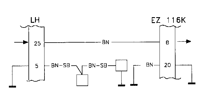
Break or grounding in the wiring between MFI#25 and DI#8.
Fault symptoms:
None apparent.
TQ1
Volvo ST, Test Box

-Disconnect the ST in accordance with QA2. Connecting The Volvo Scan Tool (ST)
-Connect the test box to 1CM and check the GND point in accordance with P3-P4.
-Continue with Checking the load signal to ICM TQ2.
TQ2
Checking The Load Signal To Ignition Control Module (1CM)
-Connect the control module to the test box.
-Install the fuse.
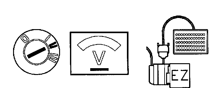
-Ignition on.
Connect a voltmeter between DI#8 and DI#20 (GND).
The voltmeter should read 200-500 mV.
If this value Is OK
Intermittent fault.
-Check the connections for loose contacts and intermittent grounding in accordance with NA3. Checking the Wiring
If the reading is approx. 7 V
-Check the wiring between the control modules for breaks.
If the reading is approx. 0 V
-Check the wiring's resistance to GND TQ3.
TQ3
Checking The Wiring's Resistance To GND
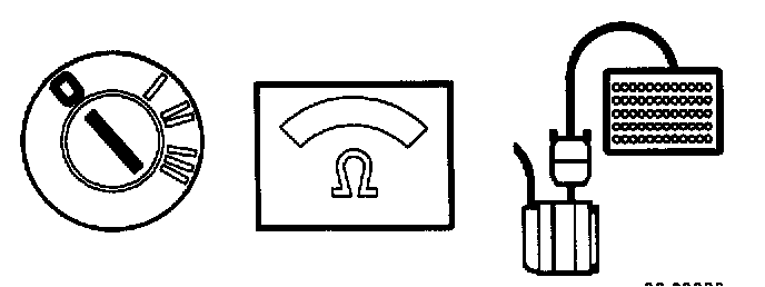
-Ignition off.
- Remove the fuse from the battery (in engine compartment (-90) or no.6 (91-).
-Disconnect both control modules.
Connect an ohmmeter between DI#8 and DI#20 (GND).
The ohmmeter should read infinite resistance.
If this value Is OK
-Try using a new control module.
If the reading is Incorrect
-Check the wiring between the control modules for grounding.