EGR Control Solenoid: Testing and Inspection
Fig. 170 SELF DIAGNOSTIC UNIT:
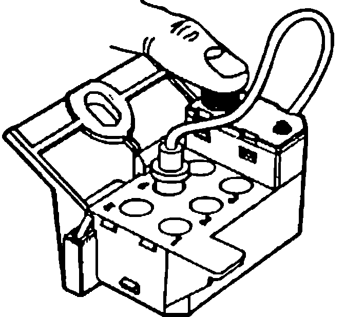
Test mode "3"
- Switch on ignition. Press test button on diagnostic unit 3 times, each time for more than 1 second. Fig. 170.
- LED will flash approx. twice per second.
- E.G.R. vacuum controller should operate in step with flashing of LED. If this occurs, vacuum controller circuit and wiring are intact.
Fig. 171 E.G.R. VACUUM BOOSTER CHECKING:
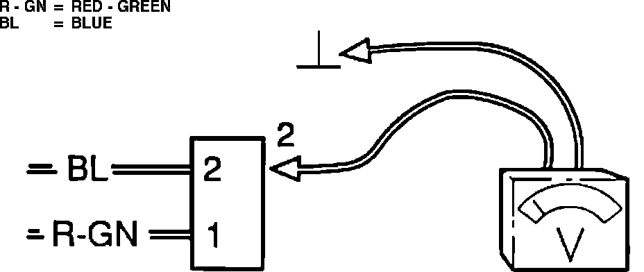
If E.G.R. vacuum controller does not operate:
- Switch on ignition. Remove vacuum controller connector and measure voltage between terminal 2 and ground, on the connector. Fig. 171.
- If voltmeter does not indicate battery voltage (12 V), check fuse and wiring between ignition switch and vacuum controller.
- Reconnect connector.
Fig. 172 E.G.R. VACUUM BOOSTER CHECKING:
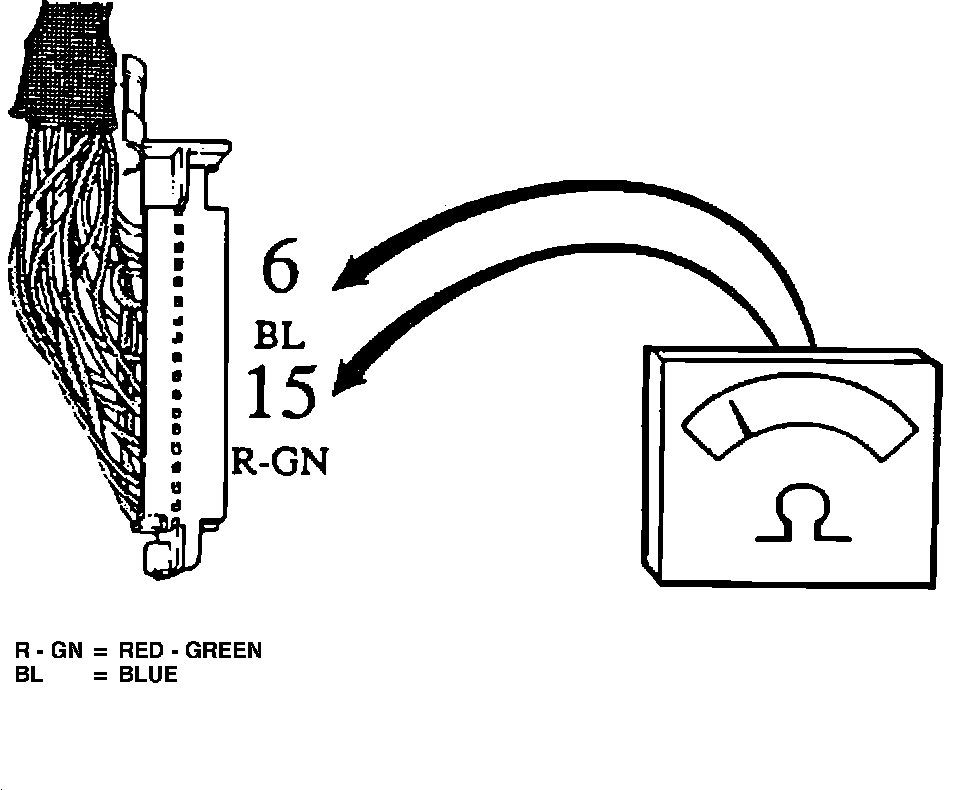
- Switch off ignition.
- Measure resistance between terminals 6 and 15 on control unit connector. Fig. 172.
- If resistance is approx. 85 ohms, (+/- 10 ohms) converter circuit and wiring are intact.
- Repeat test with another control unit.
If resistance is different:
- Check vacuum controller wiring and connections. Measure vacuum controller resistance at vacuum controller connector. Repair or replace as required.