Driveshaft - Modifications
SECTION4
GROUP
45
NO.
904
DATE:
August 1994
RE:
Guide boss for propeller shaft
964
Fault tracing
Repairs
Maintenance
REFERENCE: TP 31425/1, SECTION 4 (45), DRIVESHAFT, 700/900 1983-
Guide boss for propeller shaft, 960 4-door
A guide boss for locating the final drive propeller shaft in the multilink rear axle was introduced with effect from week 5 1994. This applies to the following chassis Nos.:
Cars built in Gothenburg: as from chassis No. 964: 043408; cars built in Kalmar: as from chassis No. 964: 043358.
Note!
Before separating the propeller shaft from the drive flange: Carefully check the shaft marking (pink dot) and ascertain if balancing bolts are installed. In appropriate cases, note the positions and lengths of the bolts.
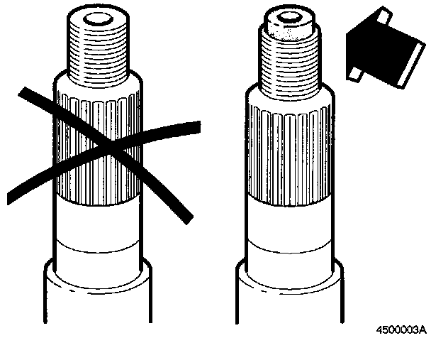
The modification means that the end of the pinion (at the end of the thread for the propeller shaft) is now provided with a guide boss as illustrated. With the addition of the boss, the drive flange splines have been shortened slightly in order to maintain the same overall pinion length.
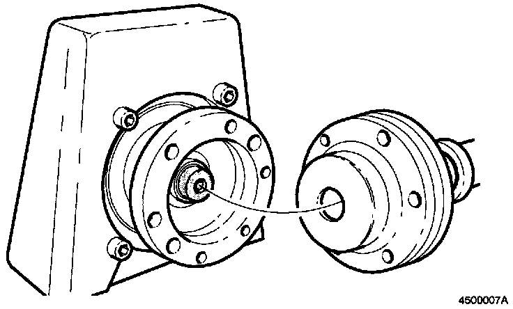
The rear cover of the CV joint on the propeller shaft has been redesigned and a new drive flange introduced to suit the modified pinion end. The oil thrower between the pinion seal and pinion front bearing have been eliminated.
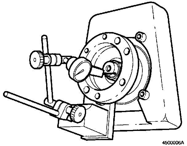
When checking the pinion runout:
Measure the pinion boss runout. The maximum permissible value is 0.04 mm. If this value is exceeded, adjust the drive flange in steps of a quarter turn (the runout may be affected by the position of the flange). Use a new nut each time the flange is adjusted. Max. torque: 180-200 N-m. Recheck the runout.
The propeller shaft is marked with a pink dot. In all cases, this is or should be located opposite the highest point on the pinion guide boss, as close as permitted by the CV joint and the pitch of the drive flange holes.
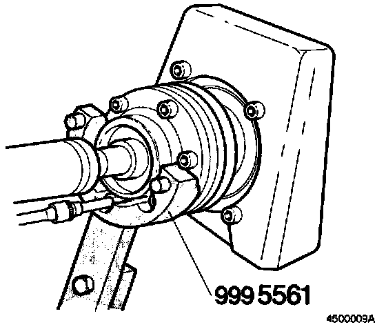
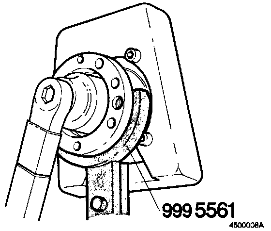
A new special tool (counterhold), P/N 999 5561, has been developed Use the tool when removing and reinstalling the propeller shaft (left-hand illustration), and when removing and reinstalling the drive flange (right-hand illustration).
When removing the drive flange: Swing the support block on the tool up into position to support the weight of the final drive.
Balancing bolts
Balancing bolts will also be introduced as part of the new propeller shaft guide arrangement at the release of the M/Y 1995. These permit fine adjustment of the shaft balance before the car leaves the production line and later as required during repair work. This allows mounting bolts of different lengths to be used in the rear drive flange. See below for details of bolt lengths.

Note!
Before separating the propeller shaft from the drive flange: Carefully check the shaft marking (pink dot) and ascertain if balancing bolts are installed. In appropriate cases, note the positions and lengths of the bolts.
Note!
If the original propeller shaft is reinstalled, always use new bolts of the same length as before. If a new shaft is installed, use only standard bolts.

Checking overall length of propeller shaft
Condition:
Shaft must be straight and mating faces of CV joints must be parallel.
Minimum: 1557.5 +/- 0.5 mm with CV joint in fully forward position
Maximum: 1579.5 +/- 0.5 mm with CV joint in rearmost position.
Propeller shaft, 964, 3.0 engine with automatic gearbox, P/N 6843934-8
Propeller shaft, 964, 2.5 engine with manual gearbox, P/N 9143070-2
Refer to TP 31425/1, for propeller shaft installation procedure.