Signal Specification, Supplemental Restraint System Module (SRS)
Signal specification
General
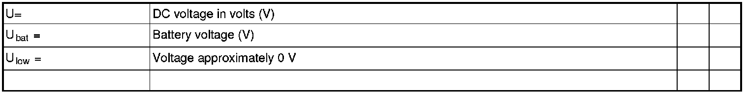
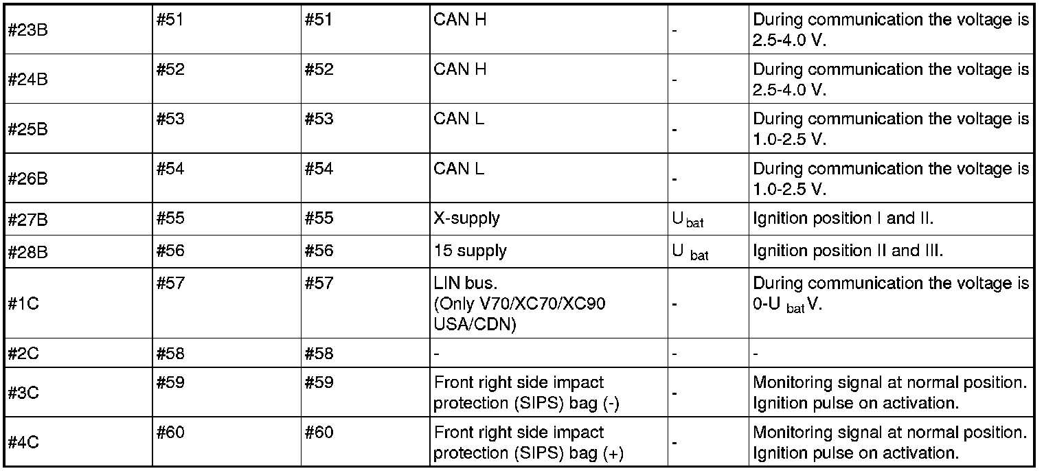
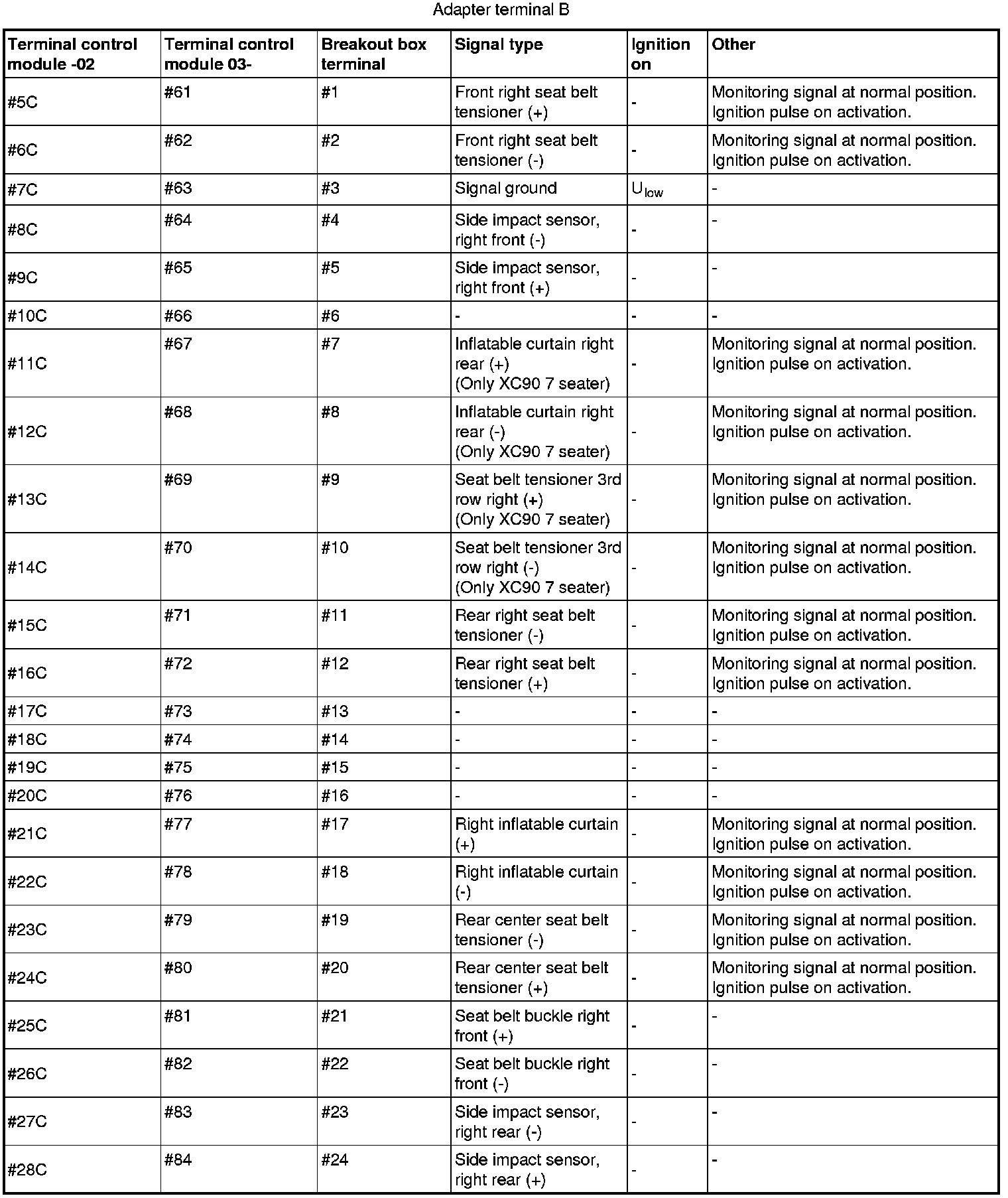
All values given below are between the terminals stated in column 2 and the ground terminal on the body for the control module.
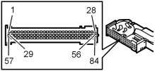
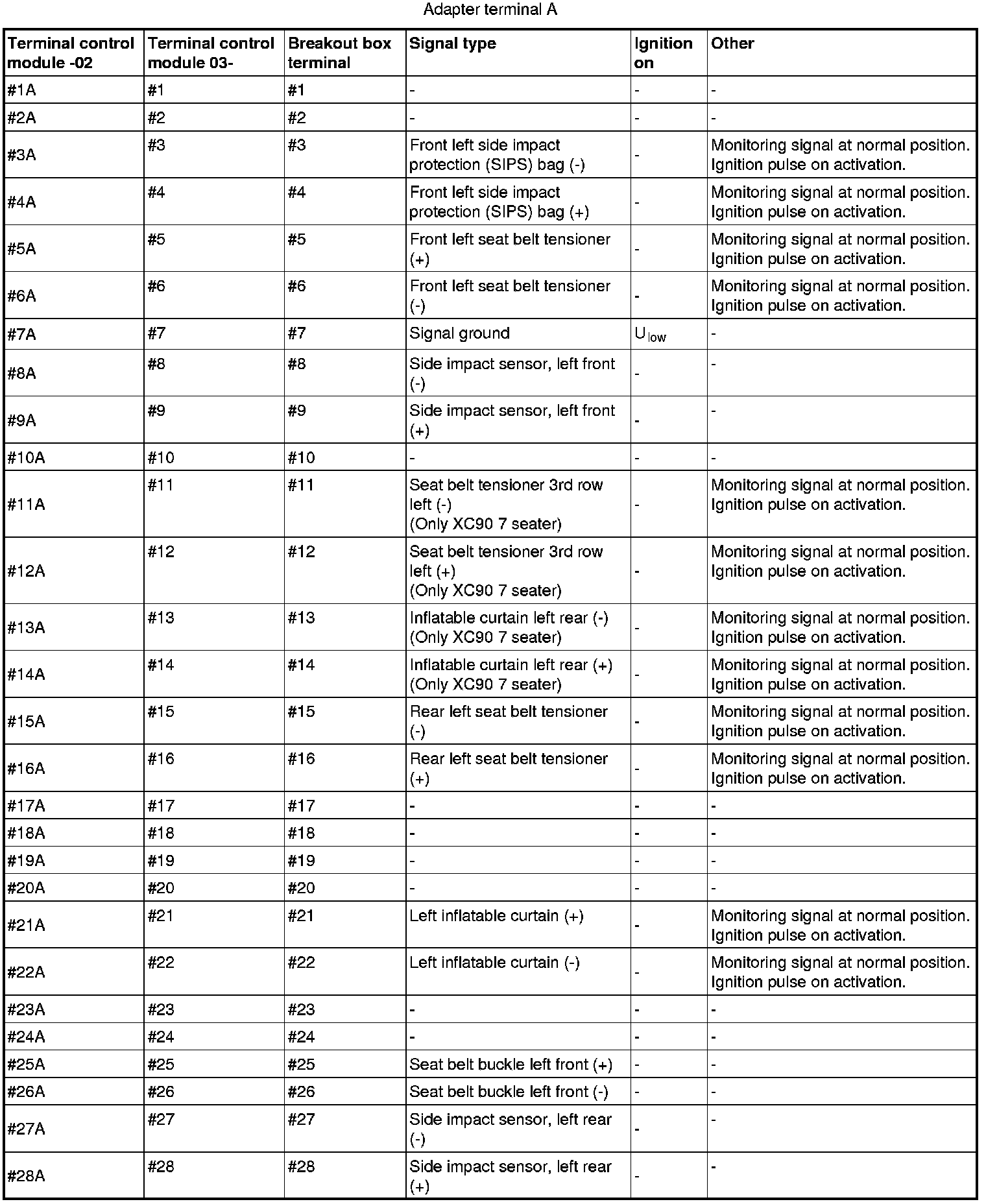
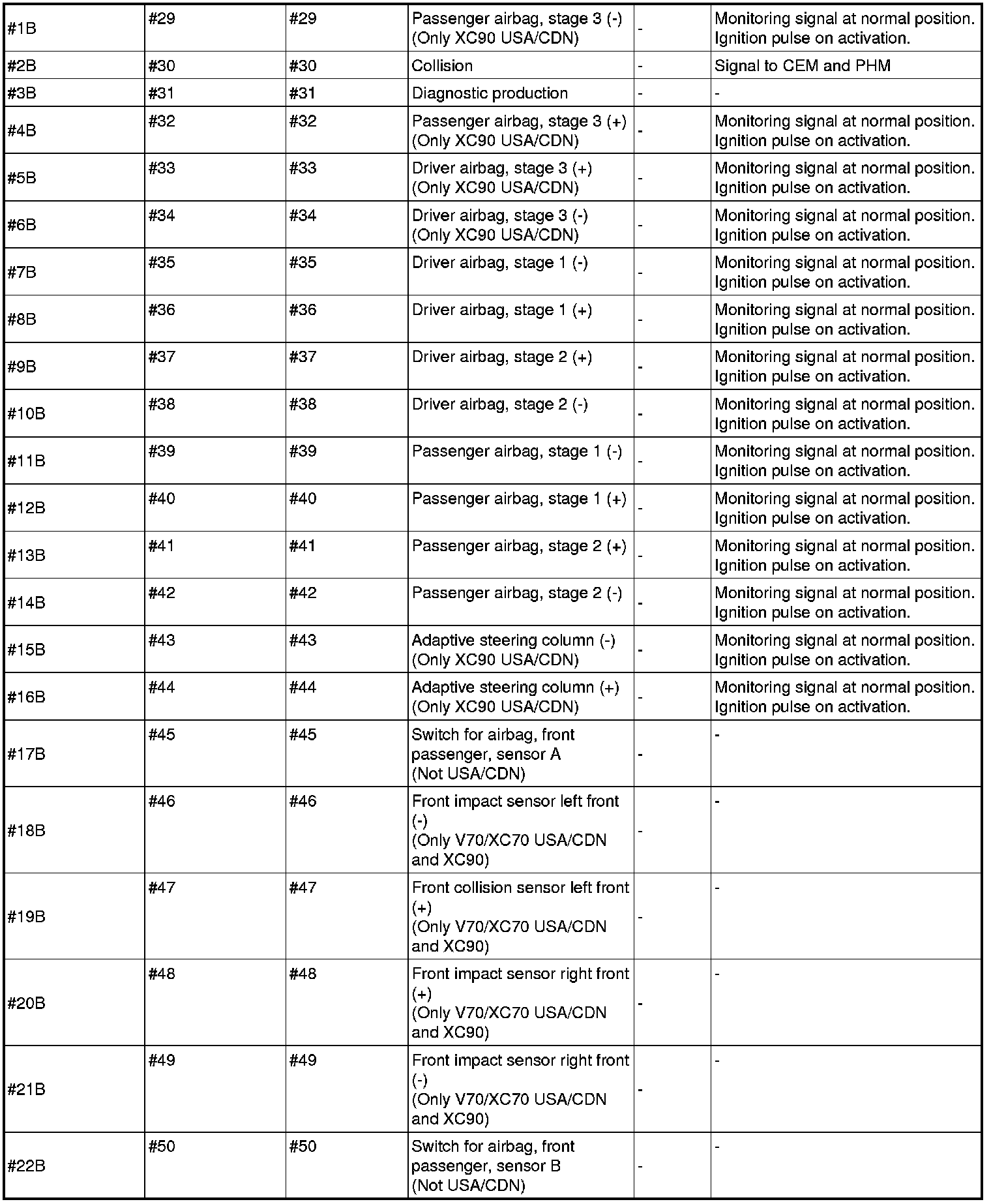
Note! It is important to connect the breakout box and check the ground terminals before taking readings. The adapter has two terminals for the breakout box. The signals in the 84-pin connector are split between adapter terminals A and B. For some VIDA fault-tracing, the connectors are numbered #1A-#28A, #1B-#28B and #1C-#28C. This is because fault-tracing is used from previous model years. From and including model year 2003, the connectors are numbered #1-#84.
- Terminals #1A-#28A correspond to terminals #1-#28
- Terminals #1B-#28B correspond to terminals #29-#56
- Terminals #1C-#28C correspond to terminals #57-#84.