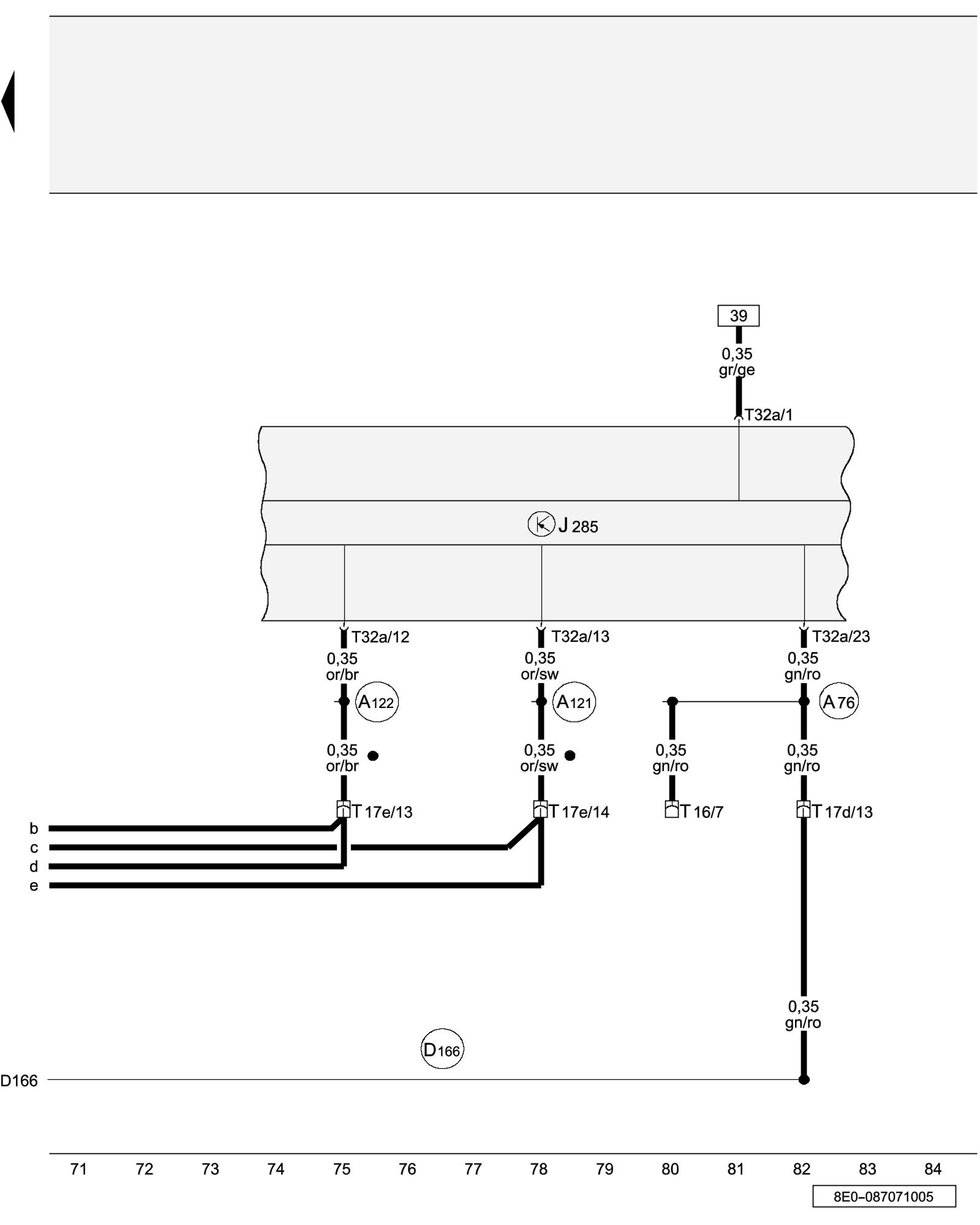
Diagram 93/7 (Tracks 71-84)
IMPORTANT NOTE:
This manufacturer uses "Track" style wiring diagrams.
For information on how to use these diagrams effectively, please refer to Diagram Information and Instructions. Diagram Information and Instructions
Instrument Cluster Control Module
ws = white
sw = black
ro = red
br = brown
gn = green
bl = blue
gr = grey
li = lilac
ge = yellow
or = orange
rs = pink
J285 - Instrument Cluster Control Module
T16 - 16-Pin Connector, black, diagnostic connection
T17d - 17-Pin Connector, red, connector station E-box, plenum chamber
T17e - 17-Pin Connector, white, connector station E-box, plenum chamber
T32a - 32-Pin Connector, green, on instrument panel insert
(A76) - K-Diagnosis Wire Connection (in instrument panel wiring harness)
(A121) - High-Bus Connection (in instrument panel wiring harness)
(A122) - Low-Bus Connection (in instrument panel wiring harness)
(D166) - K-Diagnosis Connection (in engine wiring harness)
^ - CAN-Bus (Data bus)
Previous Diagram 93/6 (Tracks 57-70)