Fuel Delivery Rate, Checking, Vehicles With FSI Engines or TFSI Engines Through MY 2012
Fuel Delivery Rate, Checking, Vehicles with FSI Engines or TFSI Engines through MY 2012
Special tools, testers and auxiliary items required
• Fuel Inj. Pressure Gauge-CIS (V.A.G 1318)
• Adapter (V.A.G 1318/10-12) and Adapter (V.A.G 1318/15)
• Remote Control (V.A.G 1348/3A) with Remote Control for VAG 1348 (V.A.G 1348/3-3)
• Connector Test Set (V.A.G 1594C)
• Measuring container, fuel-resistant
Procedure

- Follow all test requirements. Refer to => [ Test Conditions ] Initial Inspection and Diagnostic Overview.
- Remove the rear bench seat.
- Remove the locking flange cover - arrows -.
- Disconnect the connector - 1 - on the locking flange.

- Connect the (V.A.G 1348/3A) using the (V.A.G 1348/3-3) and cable from the (V.A.G 1594C) to the terminal - 1 -.

- Tape (V.A.G 1348/3-3) with insulating tape - arrow - to prevent a short circuit.
- Connect the connector terminal - 5 - to the chassis Ground (GND) with an adapter cable from the (V.A.G 1594C).
- Route (V.A.G 1348/3A) toward the front in the engine compartment.
- Remove the center plenum chamber cover.
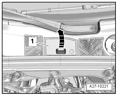
- Release the retainer - arrow A - and open the cover - arrow B -.

- Connect the alligator clip to the battery jump start terminal (U6) - A - in the terminal 30 wire junction 2 (TV22) in the plenum chamber.
- Open the fuel filler door.

- Remove the fuel filler cap - arrow -.
- Remove the air duct - arrows -.

- Remove the vacuum hose - 3 - from the connection on the air guide pipe.

- Remove the air guide pipe by loosening the hose clamp - 4 - and opening the clips - arrows -.
• Ignore - 1 and 2 -.
- Disconnect the vacuum line - 1 -.

- Remove the air filter housing and, if applicable, disconnect the electrical connector - 2 - on the rear side at the intake air switch-over valve (N335).

There is a risk of injury because the fuel is under high pressure.
• To reduce pressure in fuel system, lay a clean cloth around the connector and carefully loosen connector.
- Remove the fuel supply line from the high pressure pump - arrow -.
- Connect the fuel injection pressure gauge (V.A.G 1318) with the adapters (V.A.G 1318/11) and (V.A.G 1318/15) in the fuel line.
- Push an assisting hose - arrow - onto it and hold it into a measuring container.
- Open the shut-off valve on the pressure gauge.
• The lever points in the direction of flow.
- Generate pressure in the fuel system by pressing the switch on the remote control and slowly closing the shut-off valve on the pressure gauge.
• Specified value: 4 bar (58 psi) positive pressure.
- From this point on do not move position of shut-off valve.
- Empty measuring container.
- Press the remote control switch for 15 seconds.

- Compare quantity of fuel delivered with minimum delivery rate in diagram (cm3/15 s).
• Voltage at the fuel pump with engine stopped and pump running is approximate. 2 volts less than battery voltage.
If minimum delivery quantity is not obtained, the following malfunctions may be present:
• The fuel lines are pinched.
• The fuel filter is clogged.
• The fuel pump is faulty.
Assemble in reverse order of disassembling. Note the following:
• Secure all hose connections with hose clamps of the same type as those equipped by the factory. Refer to the Parts Catalog.
- Remove the (V.A.G 1318) and the hose lines.
- Install the right locking flange cover. Refer to => [ Locking Flange Cover - Tightening Specifications ] Fuel Tank With Attachments Overview.
- Install the rear bench seat.
- Install the air filter housing.