Battery
Battery
Observe notes on contact corrosion. Refer to => [ Contact Corrosion ] Contact Corrosion.
Removing
Pollution risk.
• Battery and sulfuric acid disposal regulations must be followed when disposing of batteries.
TDI (SCR) vehicles
• After the ignition is switched off, the reducing agent goes from the metering line to the reducing agent injector (N474) and back into the reducing agent active chamber.
• Wait until all the reducing agent has been returned before working in this area. This could take up to 10 minutes after switching off the ignition.
• Only after this is complete can the battery be disconnected. Again, this could take up to 10 minutes after switching off the ignition.
- Switch off ignition and remove ignition key.
2-door
- Lift the luggage compartment floor and engage it on the body.
- Remove the nut - 1 - and the tool kit cover - 2 -.
5-door

- Remove the luggage compartment floor panel cover.
- Remove the nut - 1 - and the tool kit cover - 2 -.
- Remove the subwoofer, if applicable.
Negative terminal cover - version I

- Remove the tool kit mount - 3 -.
- Remove the bolts - A arrows -.
- Remove the retaining bracket - 2 - for the vehicle tool kit cover.
- Release retaining clips - B arrows - using a screwdriver and remove ground terminal cap - 1 -.
- Connect the battery charger for battery support mode.
Negative terminal cover - version II

- Remove the tool kit mount - 2 -.
- Remove the screws - arrows - and the bracket - 1 -.
- Connect the battery charger for battery support mode.
All Vehicles

- Loosen nut - 4 - a few turns and remove ground cable terminal clamp from battery terminal.
- Remove the cover - 3 - over the positive terminal.
- Loosen the nut - 2 - several turns and remove the positive wire terminal clamp with fuse panel A (SA) from the battery terminal.
- Disconnect central gas venting system hose - 5 -.
- Remove the bolt - 6 - on the battery mounting bracket - 7 -.
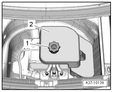
- Remove the battery - 1 - from the battery mount.
- Remove battery from luggage compartment.
Installing
• Tightening Specifications 2-door, refer to => [ Battery, 2-Door Assembly Overview ] Battery, 2-Door Assembly Overview, 5-door, refer to => [ Battery, 5-Door Assembly Overview ] Battery, 5-Door Assembly Overview.
• Only maintenance-free batteries conforming to standards TL82506 (as of December 1997) and VW75073 (as of August 2001) may be installed.
• Batteries from the Audi Parts Program have a bottom strip-adapter for adapting to different grip channels. For information on how to use the base strip adapter, if applicable, see the battery operating instructions.
- Insert battery in battery mount so that base strip - 1 - engages in battery mount retaining strips - arrow -.

• It should no longer be possible to move the battery.
- Position battery bracket - 7 -.
• Lug at battery bracket must engage in recess at battery base strip.
- Hand tighten battery bracket screw - 6 -.
- Connect central venting system hose - 5 - while observing notes.
- With the ignition and electrical consumers switched off, connect the battery - 1 - in the following sequence:
- Connect positive cable terminal clamp - 2 - by hand to battery positive terminal + and tighten nut.
- Close the cover - 3 - over the battery positive terminal.
• Ignore item - 4 -.
- Disconnect the connector - 1 - on the battery monitoring control module (J367) - 1 -.

- Connect the ground wire terminal clamp 3 by hand to the battery negative terminal - - - and tighten the nut.
- Connect the electrical connector on the battery monitoring control module.
- Check battery after installation for secure seating.
Negative terminal cover - version I
- Press the negative terminal cover - 1 - onto the battery.
All Vehicles
- Insert the bracket - 2 - and tighten the bolts - a arrows -.
- After replacing, adapt the battery in the Guided Fault Finding or Guided Functions mode.
- Select the function or path

- Follow the instructions on the Vehicle Diagnosis Tester display.
- Install the cover for the vehicle tools.
When the battery is connected, the following steps must be performed.
• Activate the one-touch up/one-touch down power window regulators. Refer to the owner's manual.
• Check DTC memories of all control modules and erase Undervoltage DTC if necessary.
• After connecting the power supply, the ABS warning lamp may only go out after the vehicle has been driven a few yards.