Removal and Replacement
Engine Replacement
Tools Required
* J 28467-B , DW-117 (DW110-060) Universal Engine Support Fixture
* J 39580 , (DW010-010) Power Pack Stand
Removal Procedure

1. Remove the fuel pump fuse.
2. Start the engine and repeat cranking until the remaining fuel in the fuel line is all consumed.
Caution:
Refer to Battery Disconnect Caution Battery Disconnect Caution in Cautions and Notices.
3. Disconnect the negative battery cable.
4. Drain the engine coolant. Refer to Cooling System Draining and Filling (2.5L) Service and Repair.
5. Drain the engine oil.
6. Drain the transaxle oil.
7. Drain the power steering oil.
8. Recover the refrigerant. Refer to Refrigerant Recovery and Recharging Refrigerant Recovery and Recharging in Heating, Ventilation, and Air Conditioning.
9. Remove the engine beautification cover.
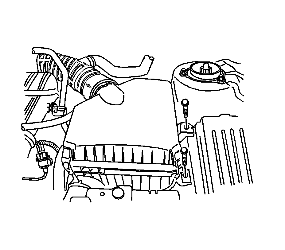
10. Remove the air filter snorkel.
11. Remove the air filter housing assembly.
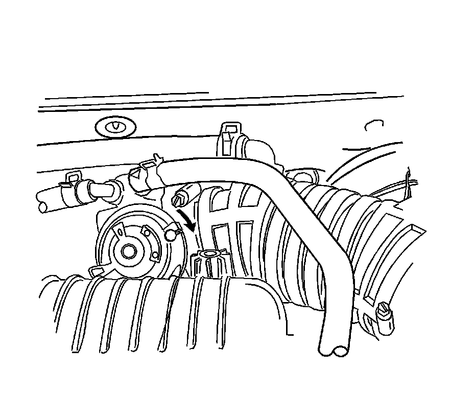
12. Remove the breather hose.
13. Disconnect the throttle cable from the throttle body assembly.
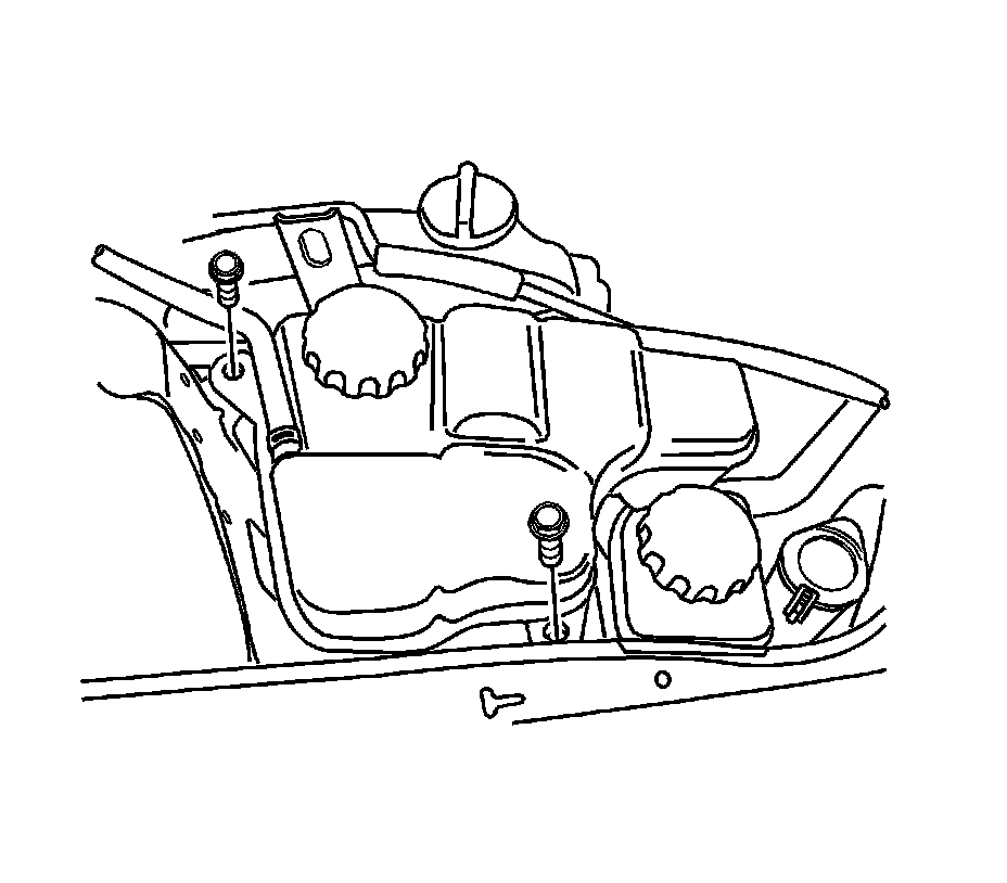
14. Disconnect the coolant reservoir hoses.
15. Remove the coolant reservoir. Refer to Radiator Surge Tank Replacement (2.5L) Service and Repair.
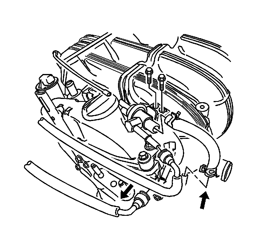
16. Disconnect the power steering pump outlet pipe.
17. Disconnect the fuel rail hose and fuel feeding/return pipe.
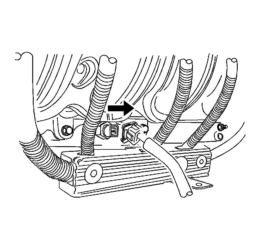
18. Disconnect the connectors on the following:
* the O2S
* EGR
* charcoal canister purge solenoid valve
* map sensor
* throttle body
* engine oil pressure sensor
* CMP sensor
* knock sensor
* VIS
* engine coolant temperature sensor

19. Detach the wiring harness from the wiring harness bracket on the cylinder block.
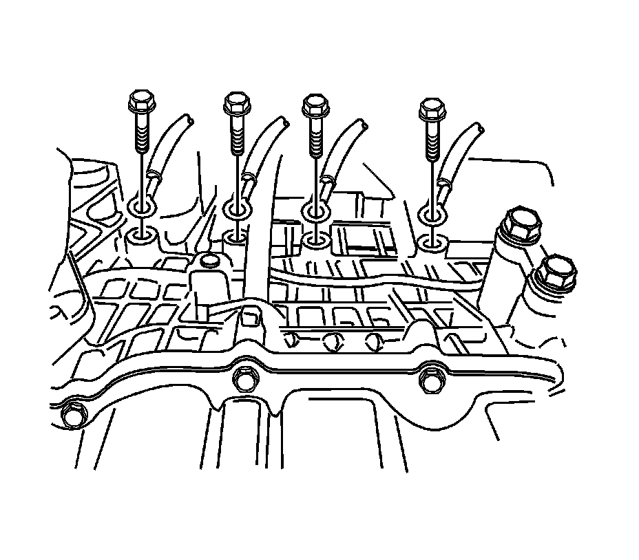
20. Disconnect the engine block ground by removing the engine block ground bolts.
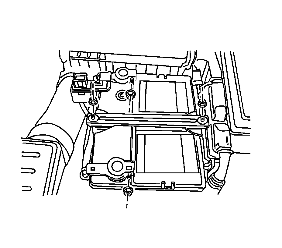
21. Remove the battery.
22. Disconnect the automatic transaxle cable.
23. Disconnect the inhibit switch connector.
24. Disconnect the connectors on the transaxle.
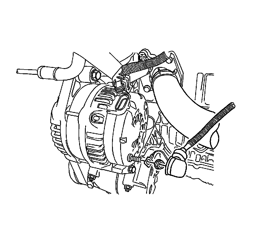
25. Disconnect the alternator connector and wiring harness.
26. Remove the upper and lower radiator hoses.
27. Remove the front wheels.
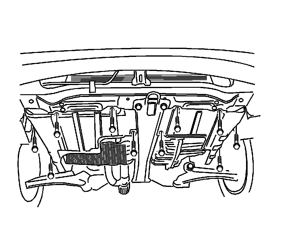
28. Remove the engine under covers.
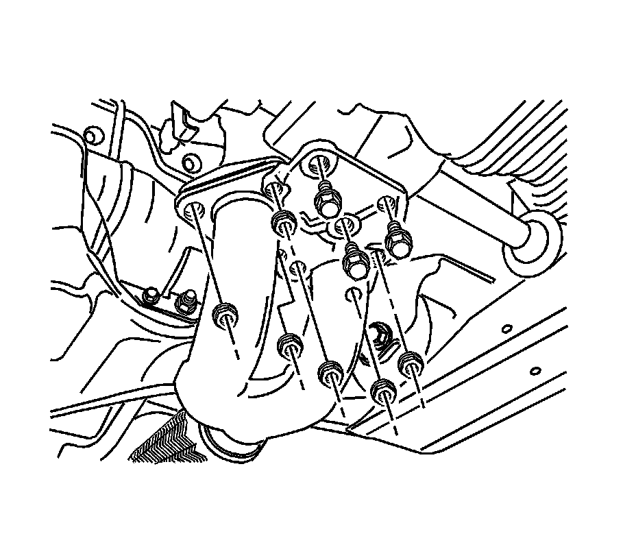
29. Remove the front axle shaft. Refer to Front Drive Axle Inner Shaft Replacement Service and Repair in Front Drive Axle.
30. Remove the front muffler. Refer to Exhaust Muffler Replacement (Rear) Exhaust Muffler Replacement (Rear)Exhaust Muffler Replacement (Front 2.5L) Exhaust Muffler Replacement (Front) in Engine Exhaust.
Notice:
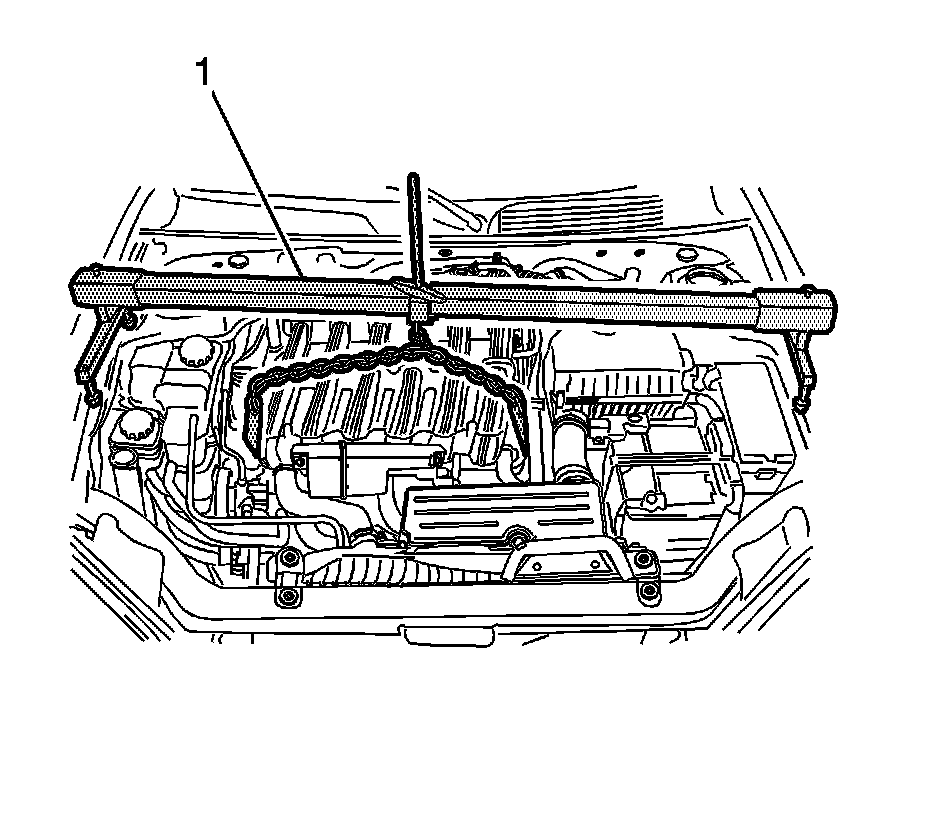
When raising or supporting the engine for any reason, do not use a jack under the oil pan, any sheet metal, or crankshaft balancer. Jacking against the oil pan may cause it to crack or break.
31. Support the engine assembly using the J 28467-B (1).
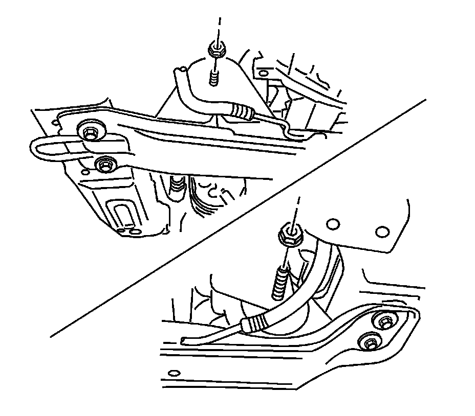
32. Remove the front engine mount bracket-to-damper bush bolt/nut and the rear transaxle mount-to-damper bush bolt/nut.
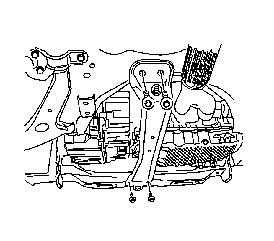
33. Remove the center front suspension member bolts and the center front suspension member.
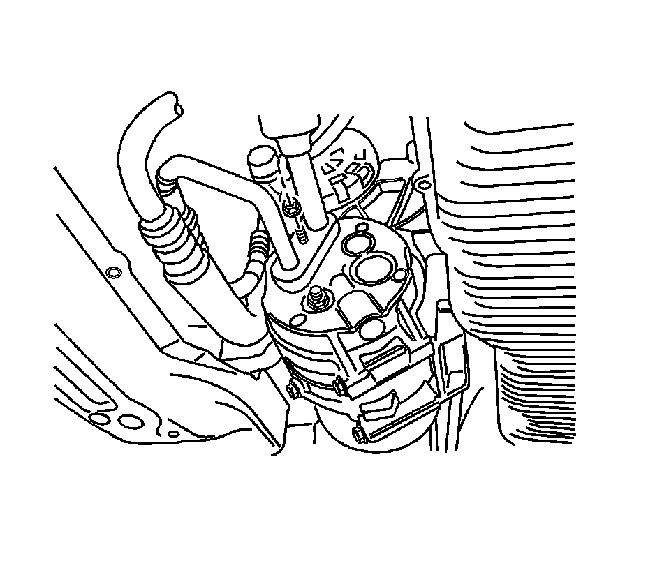
34. Disconnect the connector on the compressor.
35. Disconnect the refrigerant suction and discharge pipe block from the compressor.
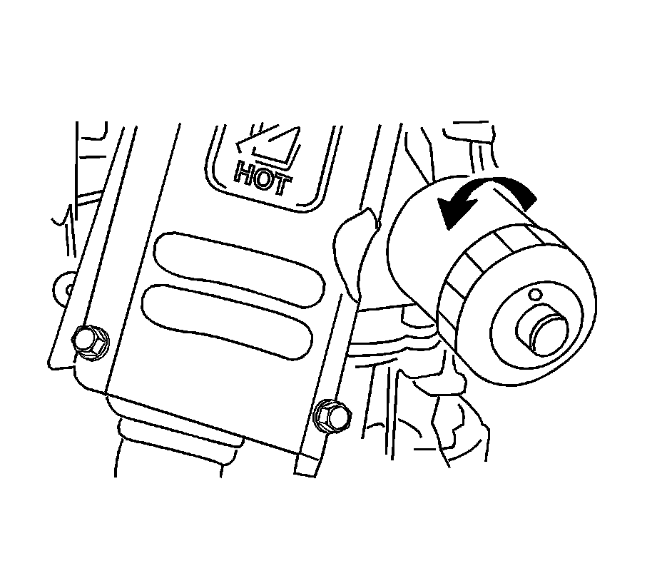
36. Remove the oil filter.

37. Support the engine and transaxle with the J 39580.
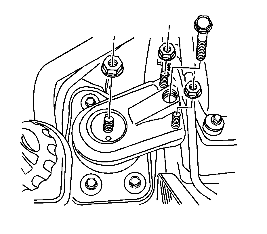
38. Remove the engine mount bracket- right hand. Refer to Engine Mount Replacement (Left Side) Engine Mount Replacement (Left Side)Engine Mount Replacement (Right Side) Engine Mount Replacement (Right Side).
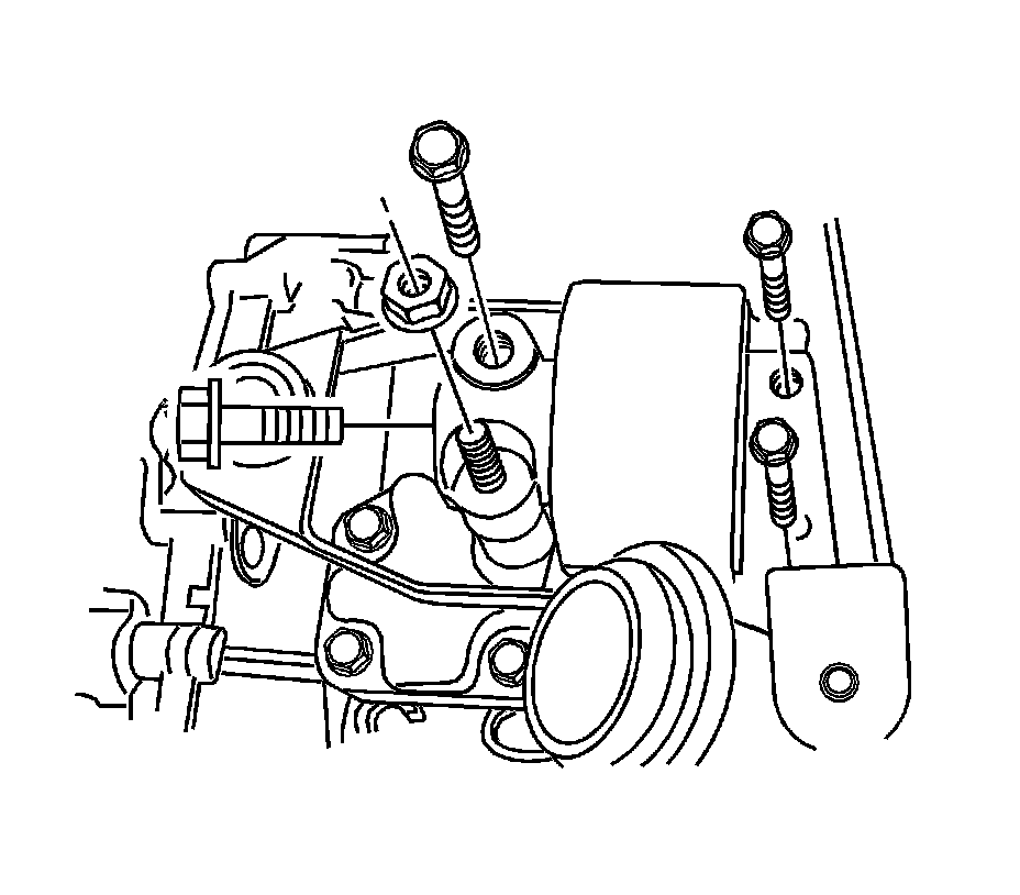
39. Remove the engine mount bracket-left hand. Refer to Engine Mount Replacement (Left Side) Engine Mount Replacement (Left Side)Engine Mount Replacement (Right Side) Engine Mount Replacement (Right Side).
40. Separate the engine and transaxle assembly from the engine compartment.
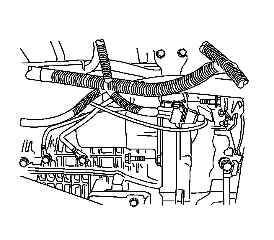
41. Remove the starter. Refer to Starter Replacement (2.5L) Removal and Replacement.
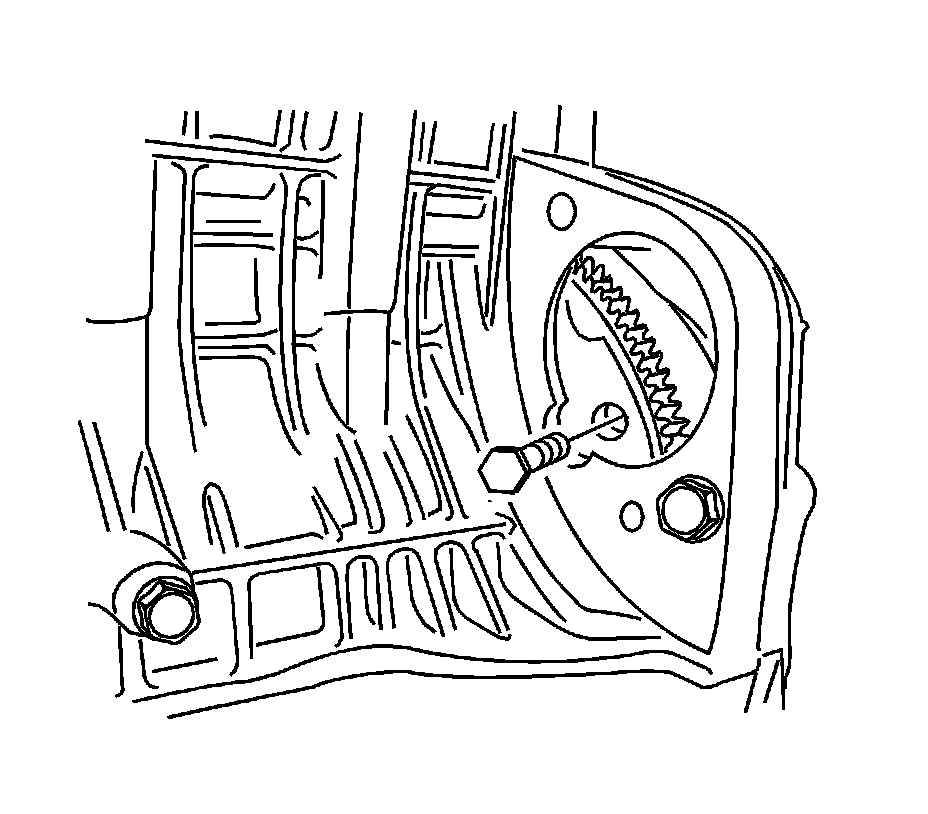
42. Remove the 3 transaxle torque converter bolts.
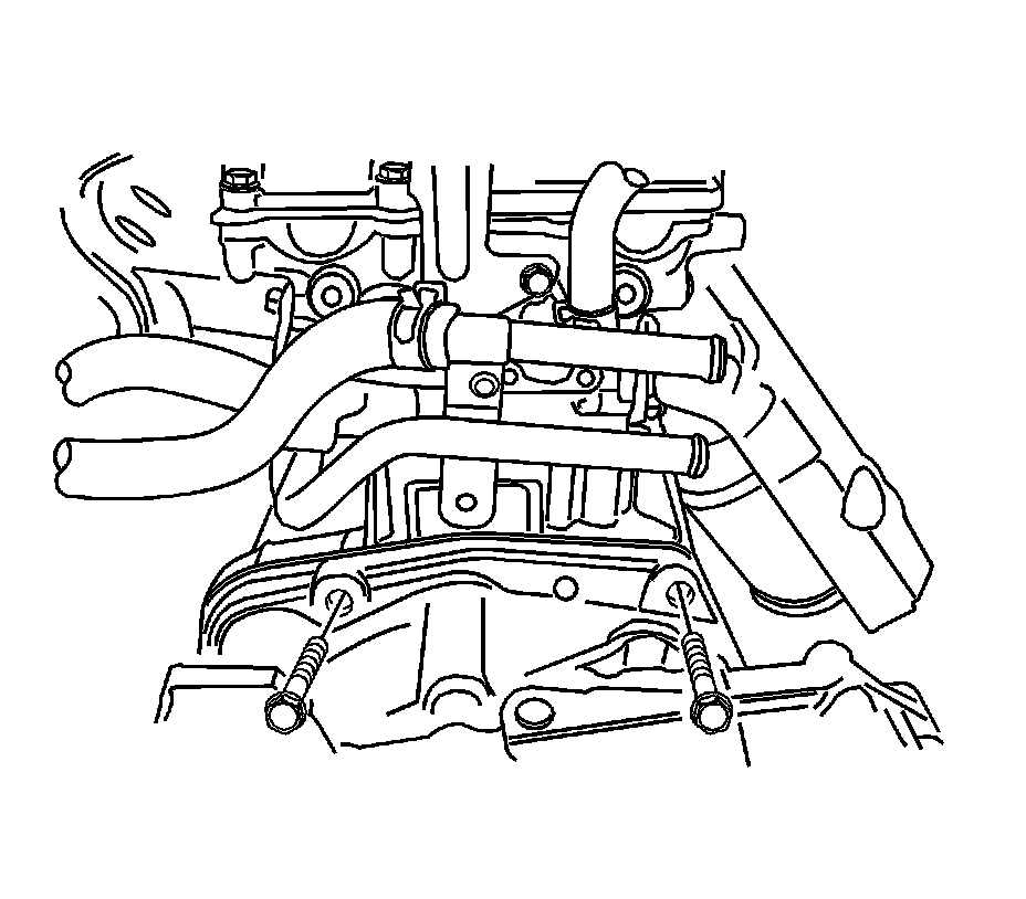
43. Remove the transaxle-to-engine block bolts.
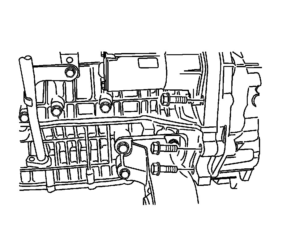
44. Remove the engine block-to-transaxle bolts.
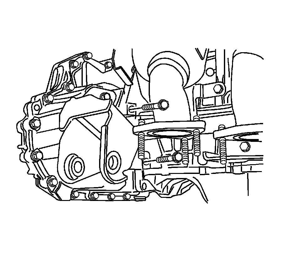
45. Remove the engine block-to-transaxle bolts.
NOTICE:
Carefully inspect the transmission and the surrounding areas to be sure no lines, hoses or wires will interfere with the transmission removal. In order to avoid damage to the transmission or the torque converter, support the transmission with a dolly jack. Do not let the torque converter fall.
46. Remove the engine assembly from the transaxle.
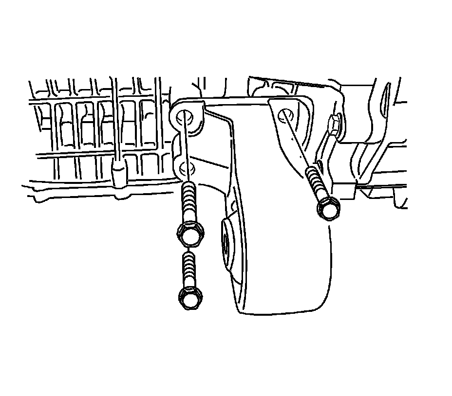
47. Remove the rear transaxle mount bracket.
48. Remove the front damper bush bracket.
Installation Procedure
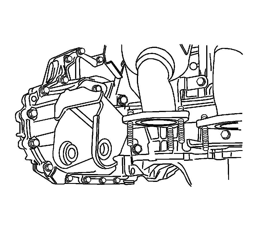
NOTICE:
Carefully inspect the transmission and the surrounding area to be sure no lines, hoses or wires will interfere with the transmission installation. When raising and moving the transmission, do not let the torque converter slip off the shaft. The transmission or torque converter can be damaged.
1. Install the engine assembly to the transaxle.
Notice:
Refer to Fastener Notice Fastener Notice in Cautions and Notices.
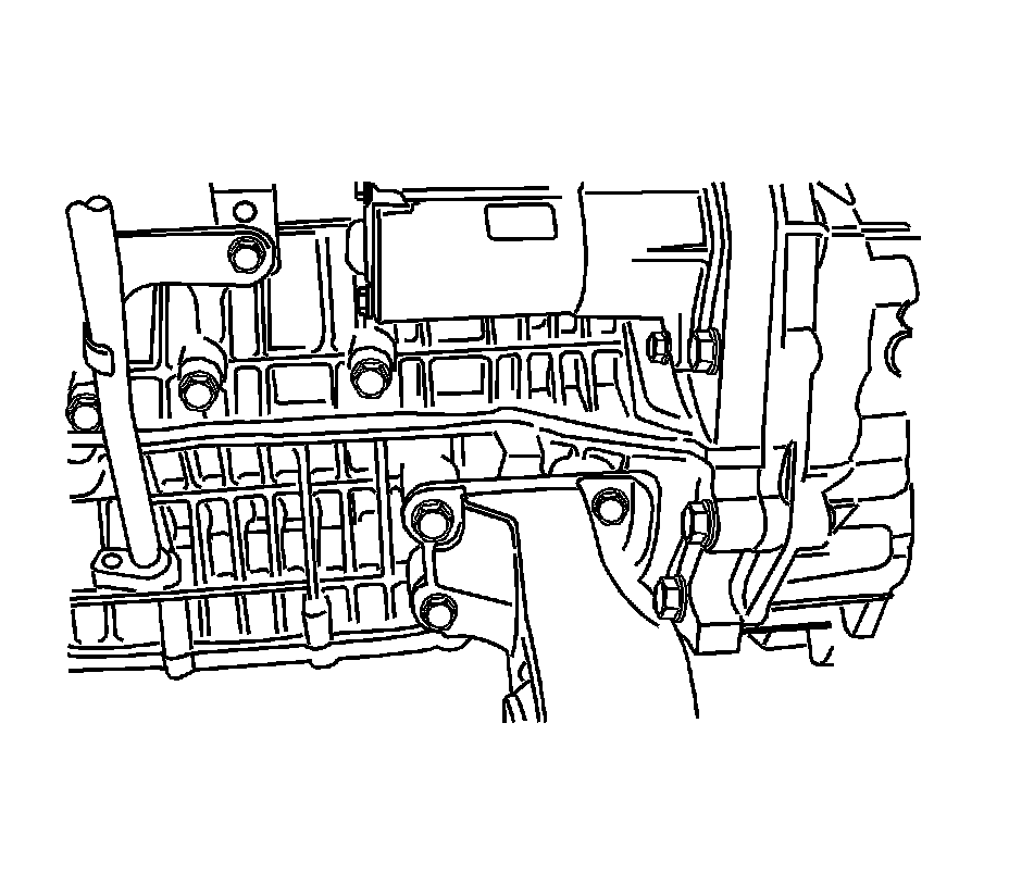
2. Install the engine block-to-transaxle bolts near the rear transaxle bracket
Tighten the engine block-to-transaxle bolts to 72 Nm (53 lb ft).
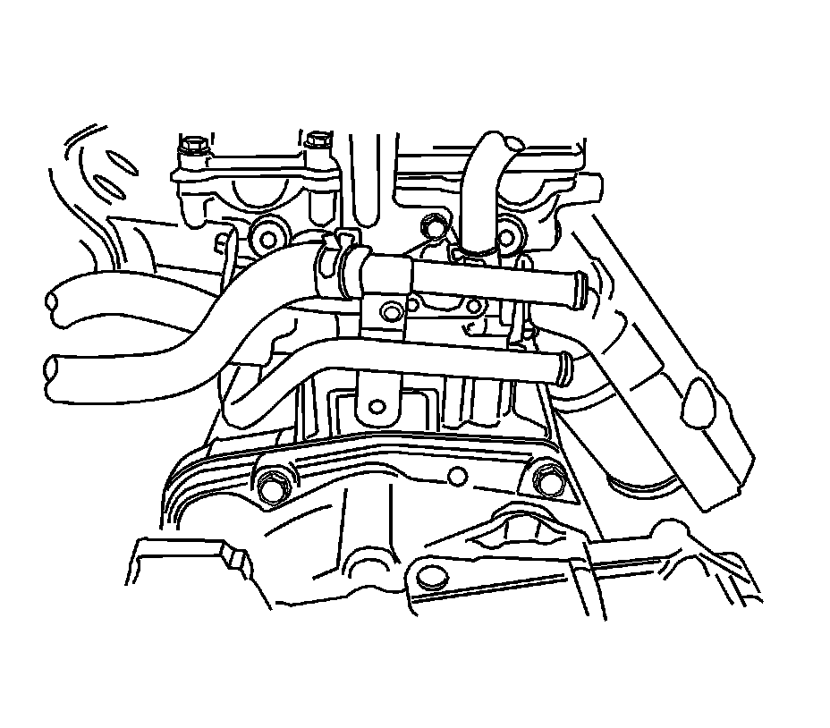
3. Install the engine block-to-transaxle bolts near the front engine mount bracket.
Tighten the engine block-to-transaxle bolts to 72 Nm (53 lb ft).
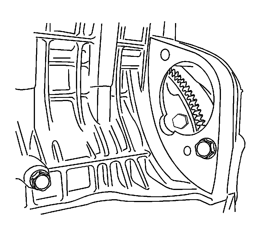
4. Install the transaxle-to-engine block bolts near the rear support bracket.
Tighten the transaxle-to-engine block bolts to 72 Nm (53 lb ft).
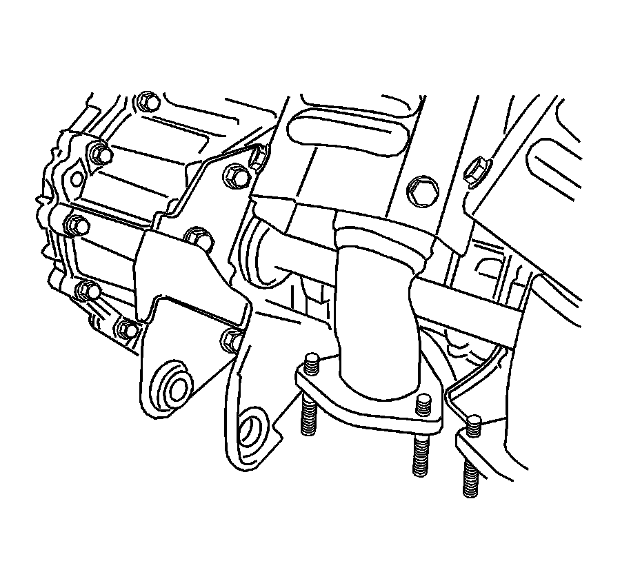
5. Tighten the 3 flexible plate-to-torque converter retaining bolts.
Tighten the transaxle torque converter bolts to 45 Nm (33 lb ft).
6. Install the rear transaxle mount bracket.
Tighten the rear transaxle mount bracket bolts to 65 Nm (48 lb ft).
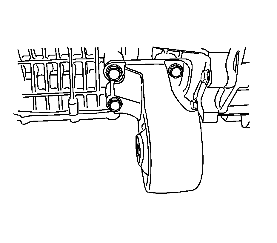
7. Install the front damper bush bracket.
Tighten the front damper bush bracket bolts to 65 Nm (48 lb ft).
8. Install the starter. Refer to Starter Replacement (2.5L) Removal and Replacement.
9. Install the engine and transaxle assembly using the J 39580 (1).
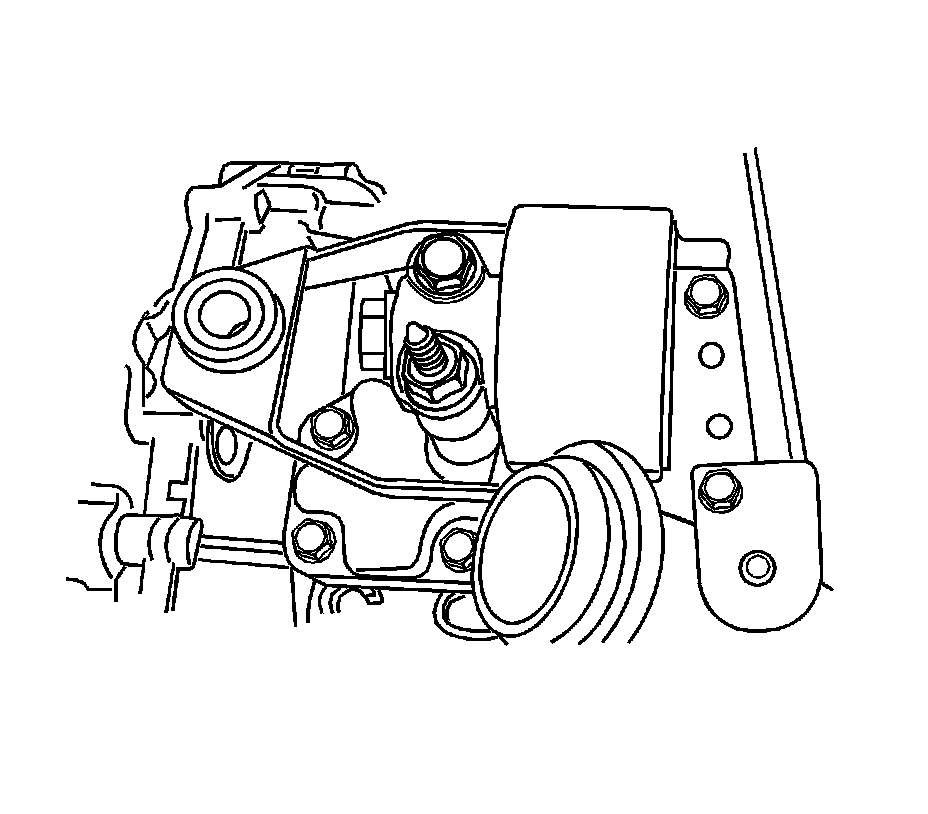
10. Install the engine mount bracket-left hand. Refer to Engine Mount Replacement (Left Side) Engine Mount Replacement (Left Side)Engine Mount Replacement (Right Side) Engine Mount Replacement (Right Side).
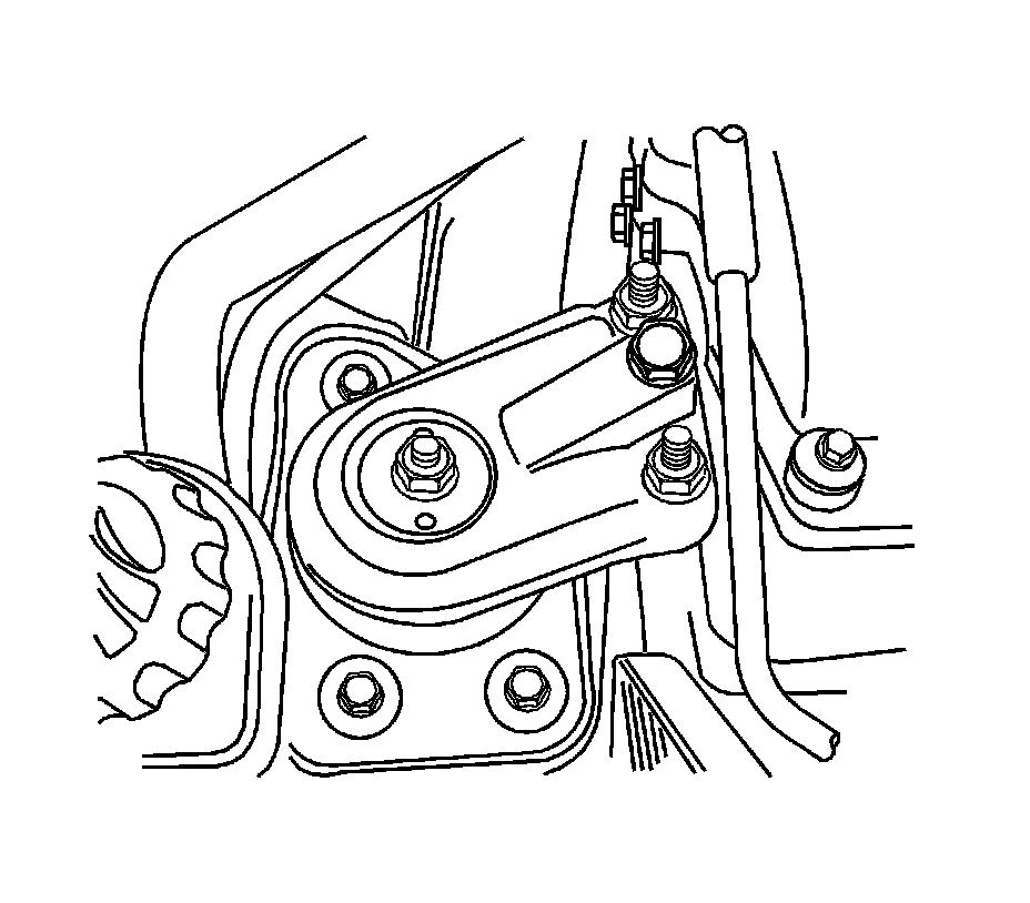
11. Install the engine mount bracket-right hand. Refer to Engine Mount Replacement (Left Side) Engine Mount Replacement (Left Side)Engine Mount Replacement (Right Side) Engine Mount Replacement (Right Side).
12. Support the engine and transaxle assembly using the J 28467-B (1).
13. Remove the J 39580.
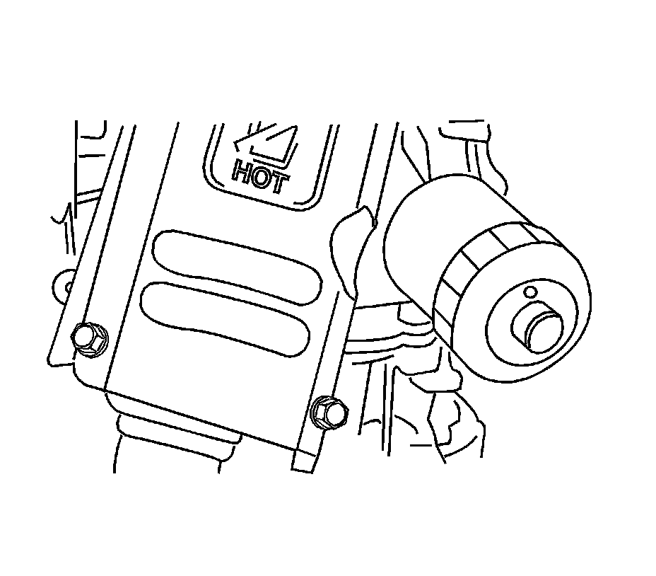
14. Install the oil filter.
Tighten the oil filter to 14 Nm (124 lb in).
15. Connect the connector on the compressor.
16. Connect the refrigerant suction and discharge pipe block to the compressor. Refer to Discharge Hose Replacement Discharge Hose Replacement in Heating, Ventilation and Air Conditioning.
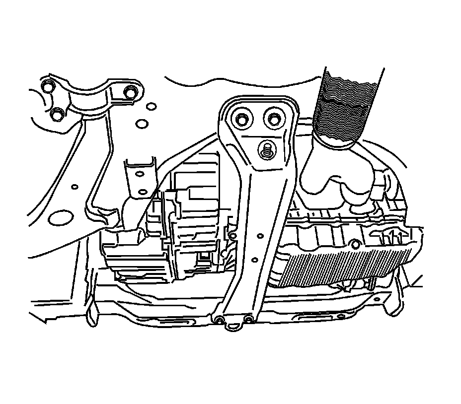
17. Install the center front suspension member.
Tighten the center front suspension, member bolts to 90 Nm (66 lb ft).
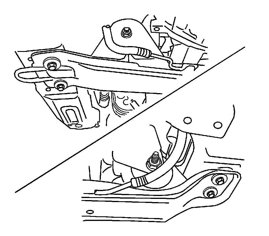
18. Install the front engine mount bracket-to-damper bush bolt/nut and the rear transaxle mount bracket-to-damper bush bolt/nut.
* Tighten the front engine mount bracket -to-damper bush bolt/nut to 80 Nm (52-66 lb ft).
* Tighten the rear transaxle mount bracket-to-damper bush bolt/nut to 80 Nm (52-66 lb ft).
19. Remove the J 28467-B.
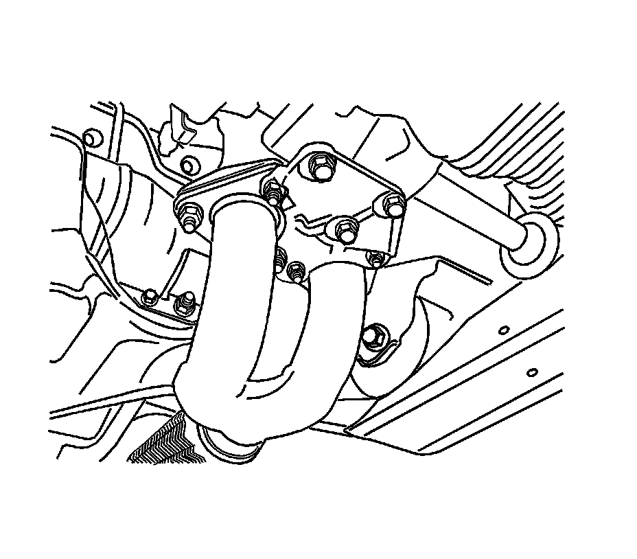
20. Install the front muffler. Refer to Exhaust Muffler Replacement (Rear) Exhaust Muffler Replacement (Rear)Exhaust Muffler Replacement (Front 2.5L) Exhaust Muffler Replacement (Front) in Engine Exhaust.
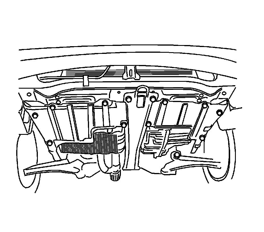
21. Install the axle shaft. Refer to Front Drive Axle Inner Shaft Replacement Service and Repair in Front Drive Axle.
22. Install the engine under cover.
Tighten the engine under cover bolts to 23 Nm (17 lb ft).
23. Install the front wheels.
24. Install the upper and lower radiator hoses.
25. Connect the alternator connector and wiring harness.
26. Connect the connectors on the transaxle.
27. Connect the inhibit switch connector.
28. Connect the automatic transmission cable.
29. Install the battery.
30. Connect the engine block grounds.
31. Attach the wiring harness to the wiring harness bracket on the cylinder block.
32. Connect all the engine control wiring connectors.
33. Connect the fuel rail hose and fuel feeding/return pipe.
34. Connect the power steering pump outlet pipe.
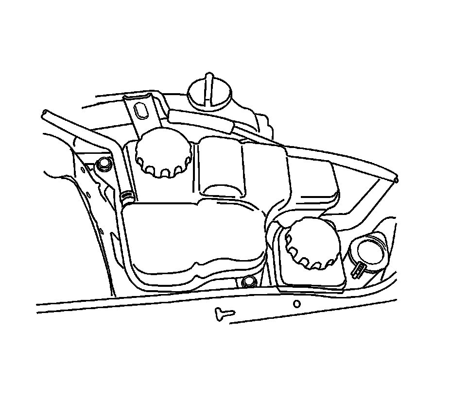
35. Install the coolant reservoir. Refer to Radiator Surge Tank Replacement (2.5L) Service and Repair.
Tighten the coolant reservoir bolts to 4 Nm (35 lb in).
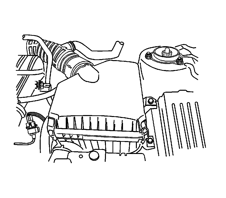
36. Connect the throttle cable to the throttle body.
37. Install the air filter housing and breather hose.
Tighten the air filter housing bolt to 10 Nm (89 lb in).

38. Install the air filter snorkel.
Tighten the air filter snorkel bolt to 6 Nm (53 lb in).

39. Install the engine beautification cover.
Tighten the engine beautification cover bolts to 10 Nm (89 lb in).
40. Connect the connectors and hoses.
41. Recharge the refrigerant. Refer to Refrigerant Recovery and Recharging Refrigerant Recovery and Recharging in Heating, Ventilation, and Air Conditioning System.
42. Fill and bleed the power steering system. Refer to Power Steering System Bleeding Power Steering System Bleeding in Power Steering System.
43. Fill the transaxle oil
44. Fill the engine oil.
45. Refill the engine coolant system. Refer to Cooling System Draining and Filling (2.5L) Service and Repair.
46. Install the fuel pump fuse.
47. Connect the negative battery cable.