Test I: The A/C Does Not Operate/Does Not Operate Correctly
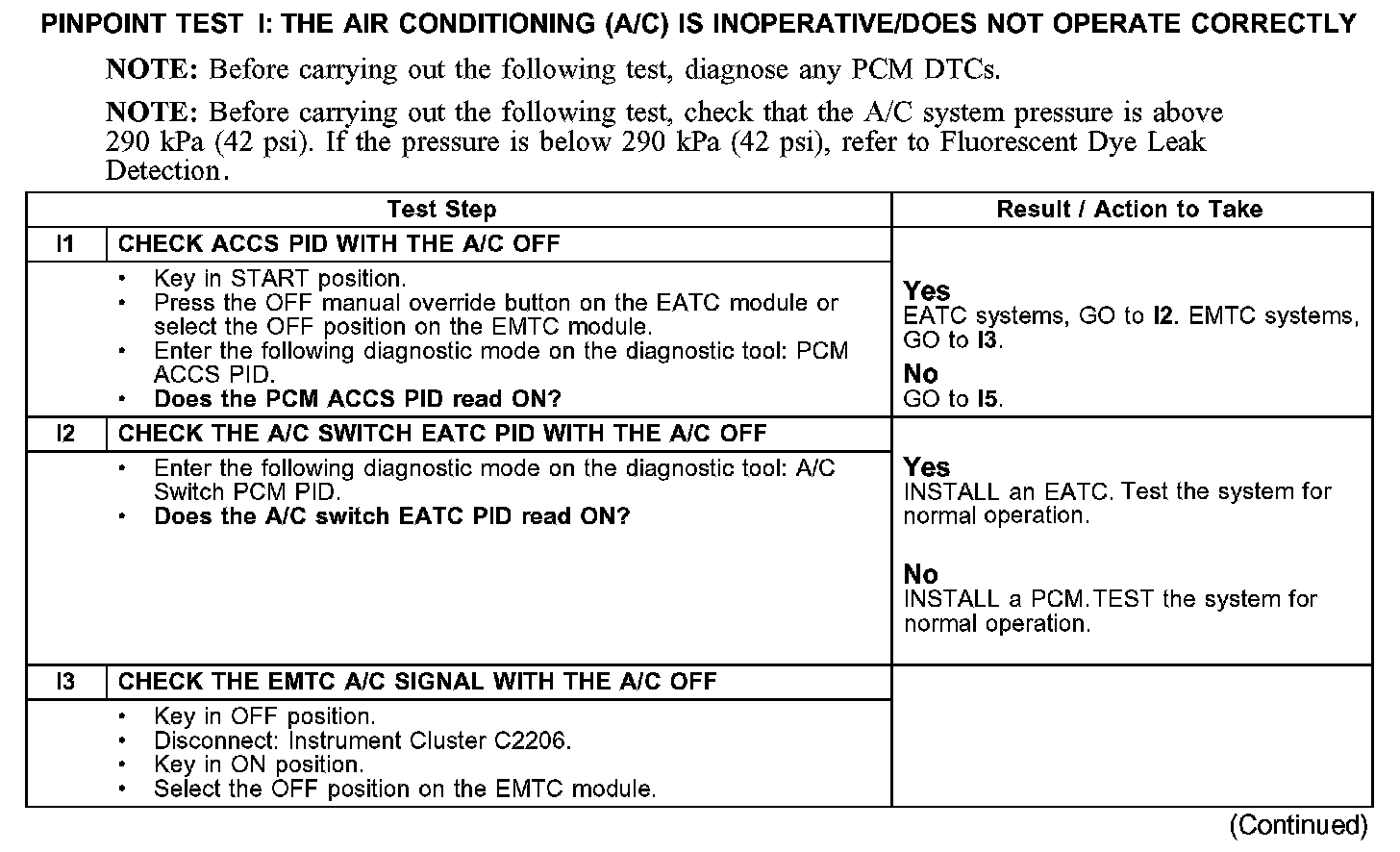
PINPOINT TEST I: THE A/C DOES NOT OPERATE/DOES NOT OPERATE CORRECTLYTest I1-I3:
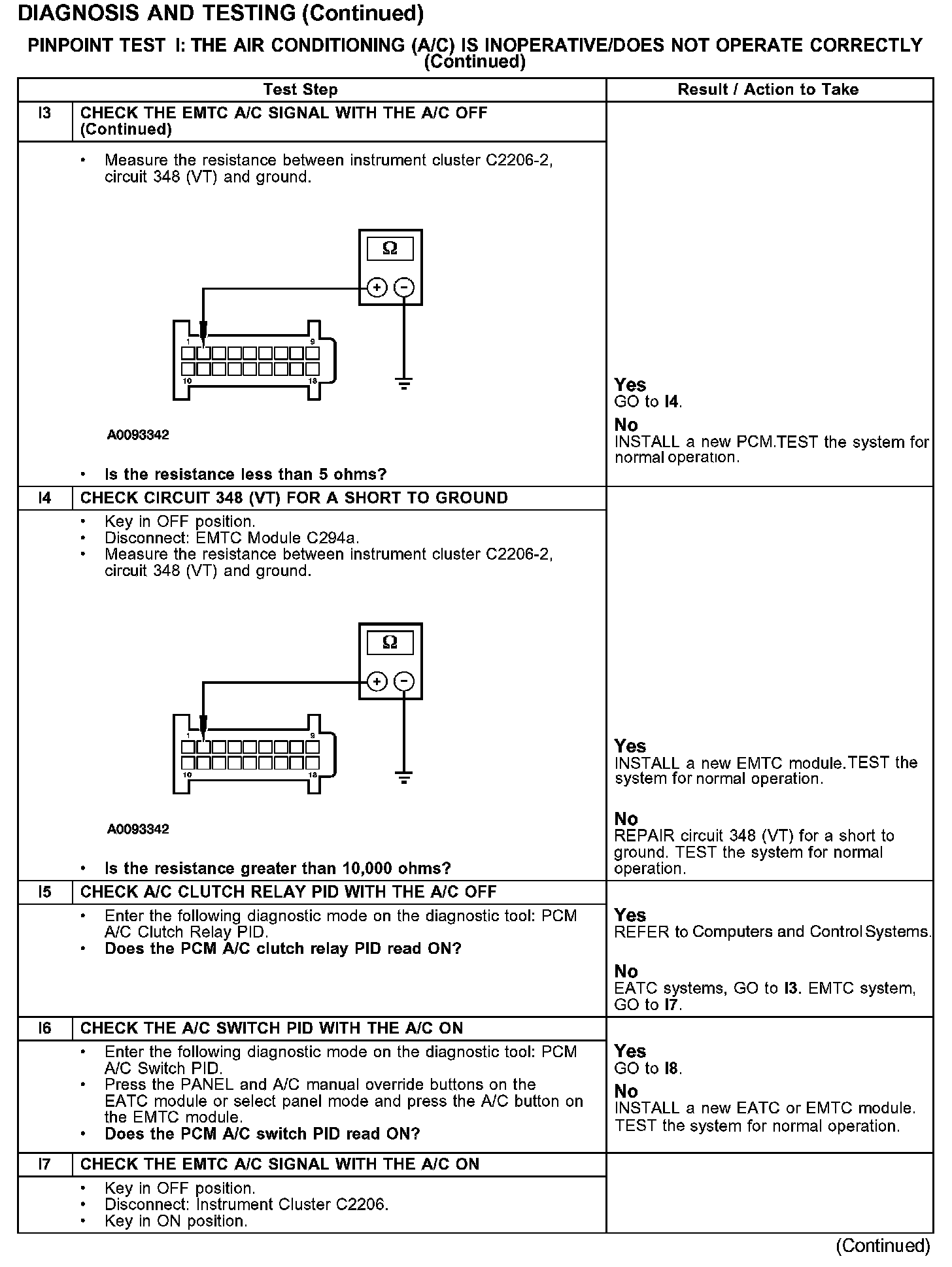
Test I3-I7:
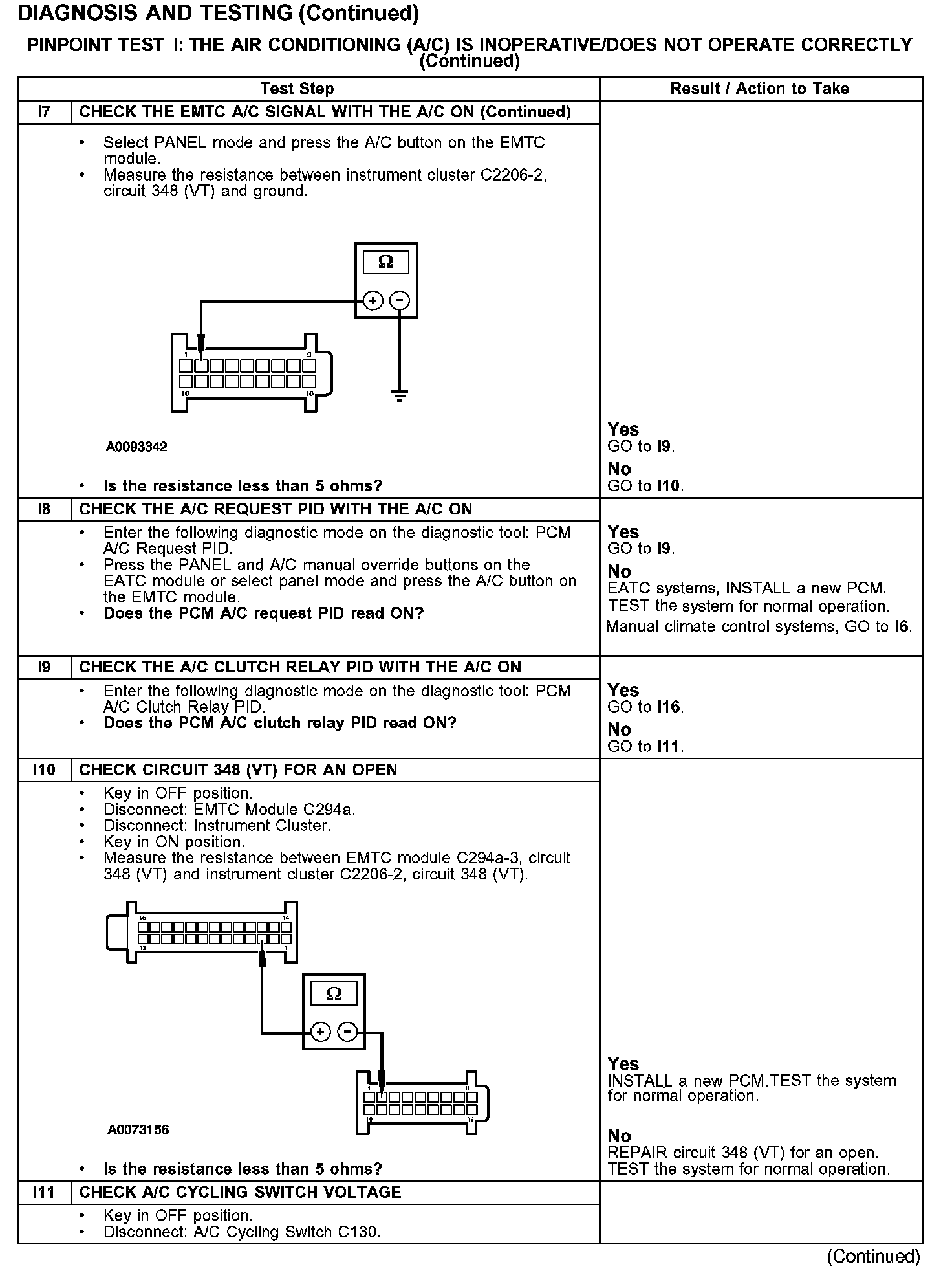
Test I7-I11:
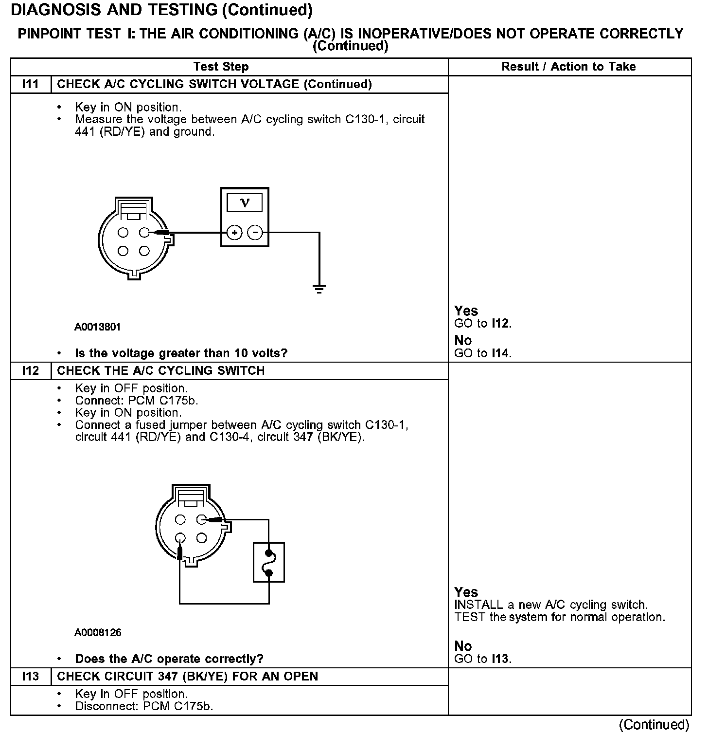
Test I11-I13:
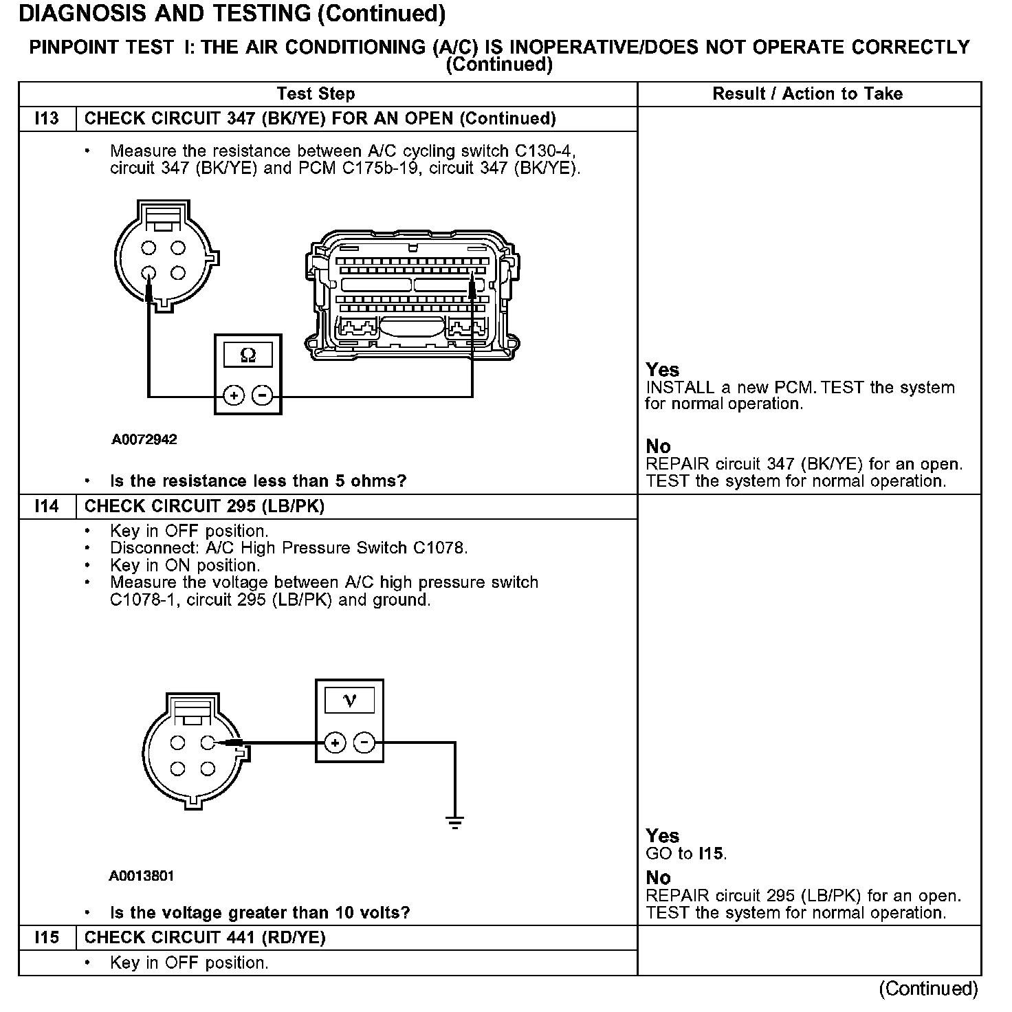
Test I13-I15:
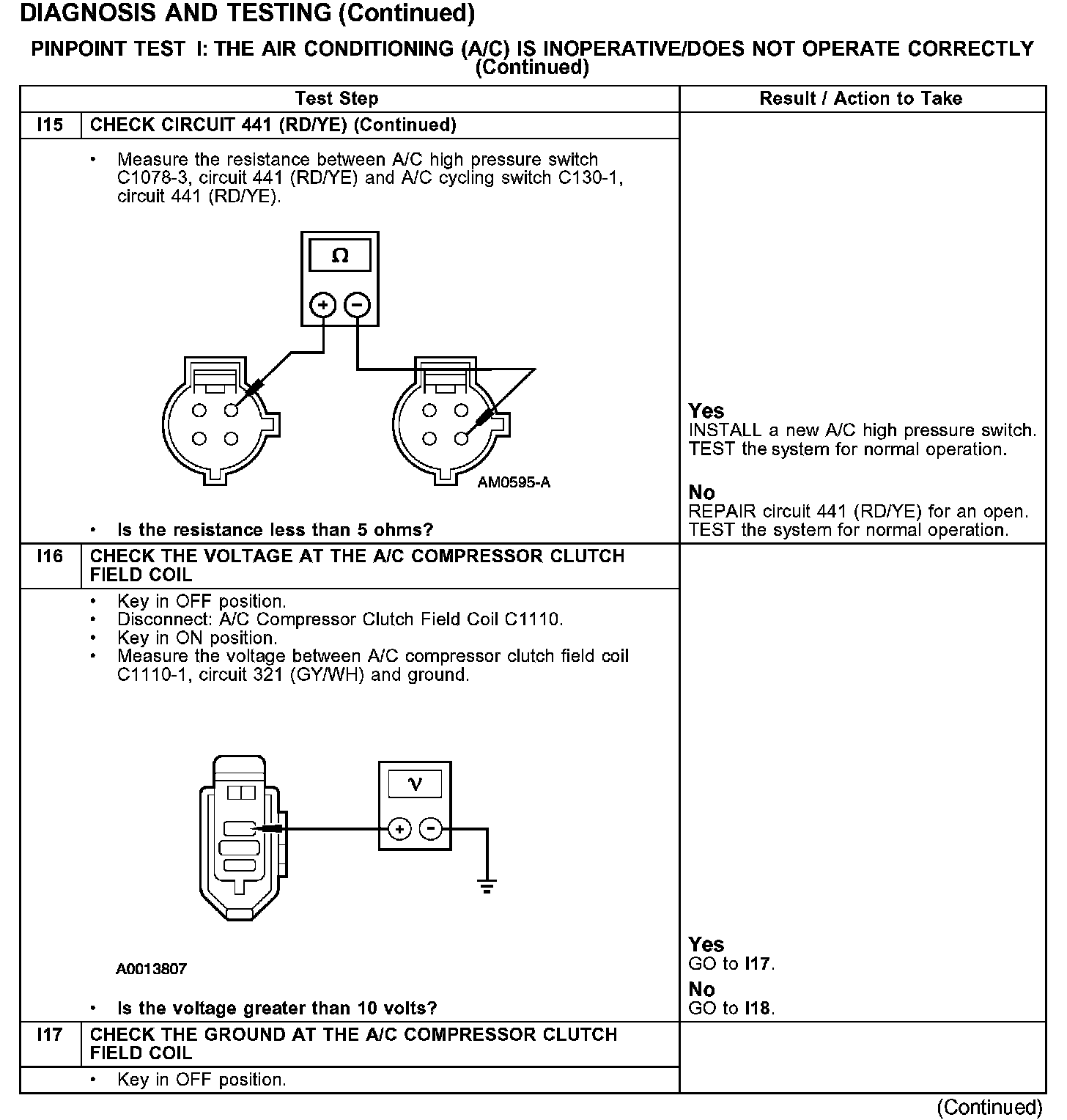
Test I15-I17:
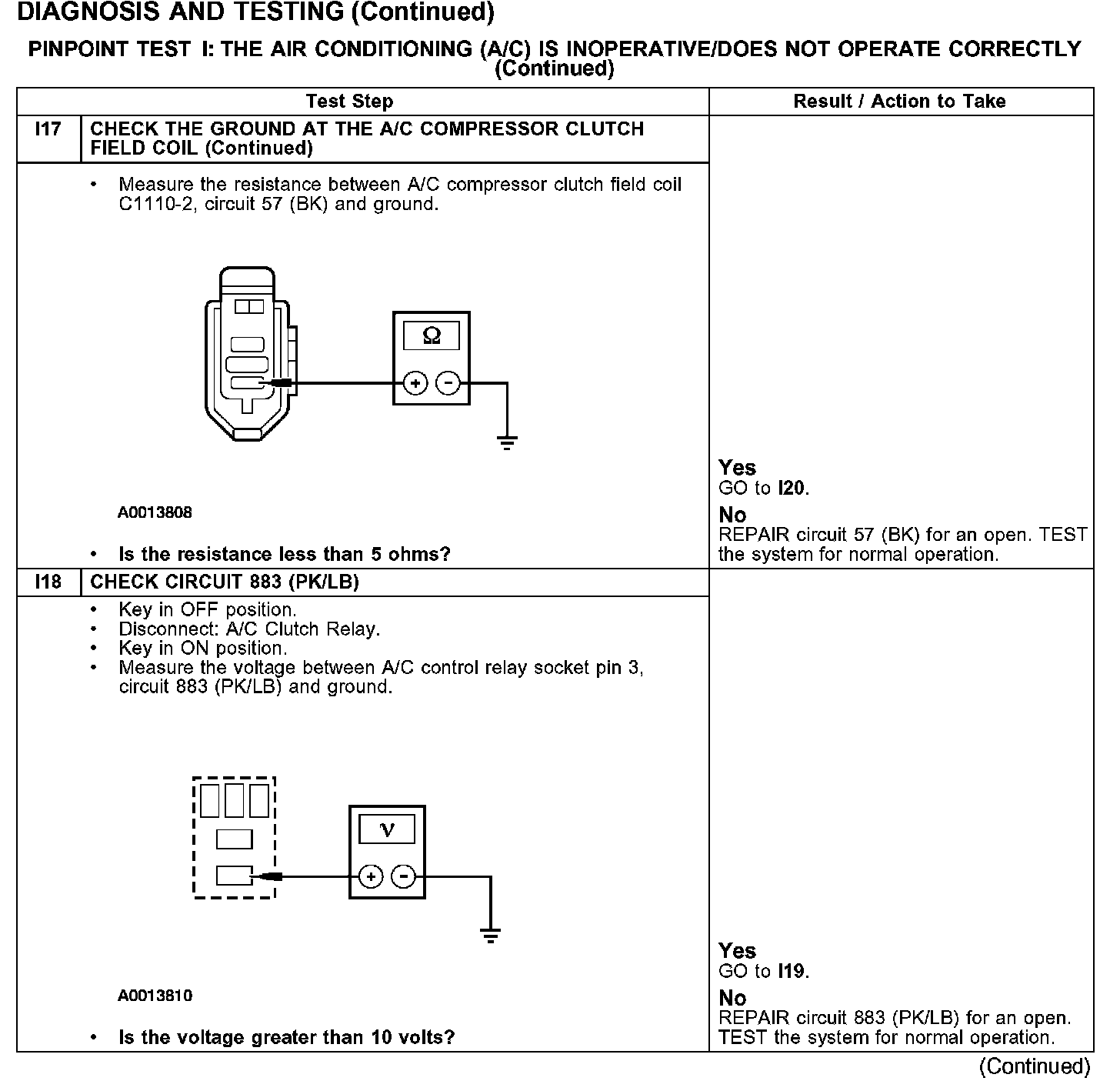
Test I17-I18:
Test I19-I21:

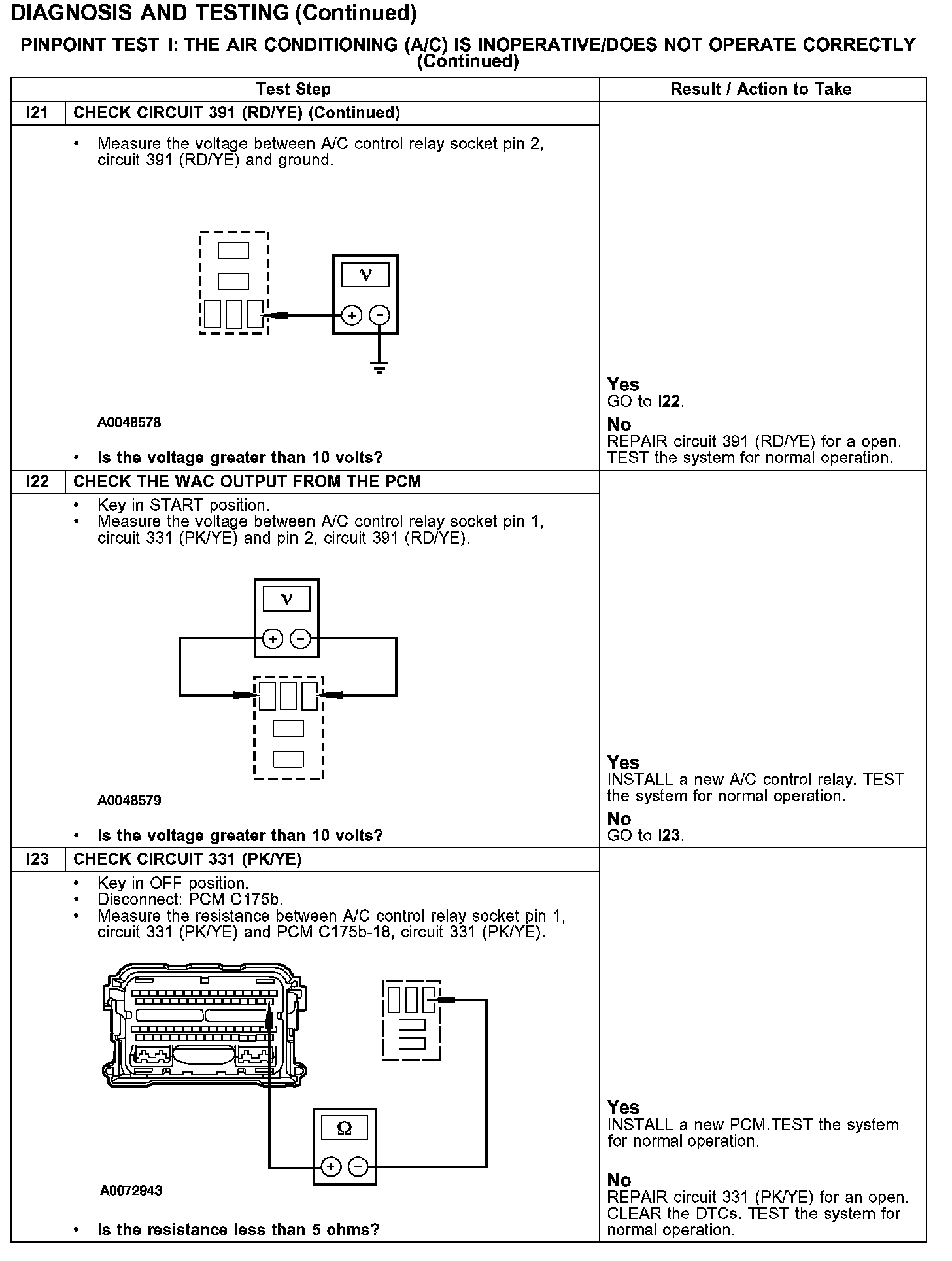
Test I21-I23:
Normal Operation
Under normal operation, when A/C is requested, a message is sent over the UBP bus to the instrument cluster, then from the instrument cluster through the CAN bus to the PCM (EATC systems) or sends voltage to the instrument cluster through circuit 348 (VT) then a message from the instrument cluster through the CAN bus to the PCM (EMTC systems). Voltage is provided to the A/C pressure cutoff switch through circuit 295 (LB/PK). The PCM receives input from the A/C pressure cutoff switch through circuit 441 (RD/YE) and through the A/C cycling switch to circuit 347 (BK/YE).
The PCM provides a ground for the A/C clutch relay coil through circuit 331 (PK/YE). The A/C clutch relay coil receives ignition voltage through circuit 391 (RD/YE). Ignition voltage for the A/C clutch relay switch is provided through circuit 883 (PK/LB). When the relay is activated, ignition voltage is supplied to the A/C clutch solenoid through circuit 321 (GY/WH). Ground is supplied for the A/C clutch through circuit 57 (BK).
Possible Causes
- An open in circuit 441 (RD/YE), 348 (VT), 883 (PK/LB), 295 (LB/PK), 347 (BK/YE), 57 (BK), 391 (RD/YE), 321 (GY/WH) or 331 (PK/YE)
- PCM
- (EATC systems) EATC module
- (EMTC systems) EMTC module
- A/C cycling switch
- A/C pressure cutoff switch
- A/C compressor clutch field coil
- A/C control relay
- A/C clutch air gap