Pinpoint Test U: The Front Display Interface Module (FDIM) Is Completely Inoperative - Vehicles With Navigation
Information and Entertainment System
Pinpoint Test U: The Front Display Interface Module (FDIM) Is Completely Inoperative - Vehicles With Navigation
Normal Operation
The Audio Front Control Module (ACM) enables the Front Display Interface Module (FDIM) by sending voltage through the enable circuit.
Video display information is sent to the FDIM (Front Display Interface Module) from the ACM (Audio Front Control Module) through a dedicated video cable. The video cable is only serviced by overlaying a new component.
If the vehicle is equipped with a rear view camera, the video feed from the camera is hardwired to the FDIM (Front Display Interface Module).
For all other display information, including the climate control and SYNC(R) system displays, messages are sent to the ACM (Audio Front Control Module) via the Medium Speed Controller Area Network (MS-CAN). The ACM (Audio Front Control Module) then alters the video feed to the FDIM (Front Display Interface Module) based on the messages it receives.
This pinpoint test is intended to diagnose the following:
- Fuse
- Wiring, terminals or connectors
- FDIM (Front Display Interface Module)
- ACM (Audio Front Control Module)
PINPOINT TEST U : THE FDIM (Front Display Interface Module) IS COMPLETELY INOPERATIVE - VEHICLES WITH NAVIGATION
NOTICE: Use the correct probe adapter(s) when making measurements. Failure to use the correct probe adapter(s) may damage the connector.
NOTE:
Failure to disconnect the battery when instructed results in false resistance readings.
U1 CHECK THE FDIM (Front Display Interface Module) VOLTAGE SUPPLY
- Ignition OFF.
- Disconnect: FDIM (Front Display Interface Module) C2123.
- Measure the voltage between the FDIM (Front Display Interface Module) C2123-1, circuit SBP09 (RD), harness side and ground.
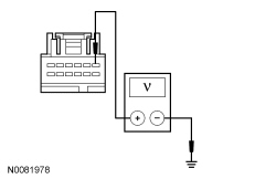
Is the voltage greater than 10 volts?
Yes
GO to U2.
No
VERIFY the Body Control Module (BCM) fuse 9 (10A) is OK. If OK, REPAIR the circuit. TEST the system for normal operation. If not OK, REFER to the Wiring Diagrams to identify the possible causes of the circuit short [1][2]Diagrams By Number.
U2 CHECK THE FDIM (Front Display Interface Module) GROUND CIRCUIT FOR CONTINUITY
- Disconnect: Negative Battery Cable.
- Measure the resistance between the FDIM (Front Display Interface Module) C2123-7, circuit GD114 (BK/BU), harness side and ground.

Is the resistance less than 5 ohms?
Yes
GO to U3.
No
REPAIR the circuit. TEST the system for normal operation.
U3 CHECK THE FDIM (Front Display Interface Module) ENABLE CIRCUIT FOR CORRECT VOLTAGE
- Connect: Negative Battery Cable.
- Ignition ON.
- Turn the audio system on using the power button on the Front Controls Interface Module (FCIM).
- Measure the voltage between the FDIM (Front Display Interface Module) C2123-5, circuit CMN23 (WH/BU), harness side and ground.

Is the voltage between 8.5 and 9.5 volts?
Yes
GO to U6.
No
GO to U4.
U4 CHECK THE FDIM (Front Display Interface Module) ENABLE CIRCUIT FOR A SHORT TO VOLTAGE
- Ignition OFF.
- Disconnect: ACM (Audio Front Control Module) C290B.
- Ignition ON.
- Measure the voltage between the FDIM (Front Display Interface Module) C2123-5, circuit CMN23 (WH/BU), harness side and ground.
Is any voltage present?
Yes
REPAIR the circuit. TEST the system for normal operation.
No
GO to U5.
U5 CHECK THE FDIM (Front Display Interface Module) ENABLE CIRCUIT FOR AN OPEN OR SHORT TO GROUND
- Ignition OFF.
- Measure the resistance between the FDIM (Front Display Interface Module) C2123-5, circuit CMN23 (WH/BU), harness side and the ACM (Audio Front Control Module) C290B-4, circuit CMN23 (WH/BU), harness side; and between the FDIM (Front Display Interface Module) C2123-5, circuit CMN23 (WH/BU), harness side and ground.

Is the resistance less than 5 ohms between the FDIM (Front Display Interface Module) and the ACM (Audio Front Control Module), and greater than 10,000 ohms between the FDIM (Front Display Interface Module) and ground?
Yes
GO to U6.
No
REPAIR the circuit. TEST the system for normal operation.
U6 ISOLATE THE VIDEO FEED CABLE
- Connect: ACM (Audio Front Control Module) C290D.
- Connect: FDIM (Front Display Interface Module) C2123.
- Install a new video feed cable by overlaying the wiring harness.
- Ignition ON.
- Operate the audio system and observe the FDIM (Front Display Interface Module) screen.
Does the system operate correctly?
Yes
The cause of the concern was an inoperative video feed cable. The system is now operating correctly.
No
GO to U7.
U7 ISOLATE THE FDIM (Front Display Interface Module)
- Install a new FDIM (Front Display Interface Module). Refer to Front Display Interface Module (FDIM) .
- Ignition ON.
- Operate the audio system and observe the FDIM (Front Display Interface Module) screen.
Does the system operate correctly?
Yes
The cause of the concern was an inoperative FDIM (Front Display Interface Module). The system is now operating correctly.
No
GO to U8.
U8 CHECK FOR CORRECT ACM (Audio Front Control Module) OPERATION
- Ignition OFF.
- Disconnect all the ACM (Audio Front Control Module) connectors.
- Check for:
- corrosion
- damaged pins
- pushed-out pins
- Connect all the ACM (Audio Front Control Module) connectors and make sure they seat correctly.
- Operate the system and determine if the concern is still present.
Is the concern still present?
Yes
INSTALL a new ACM (Audio Front Control Module). REFER to Audio Control Module (ACM) . TEST the system for normal operation.
No
The system is operating correctly at this time. The concern may have been caused by a loose or corroded connector.