Evaporator Case: Service and Repair
A/C Evaporator Housing Assembly
NOTE:Do not disassemble the A/C evaporator housing (19850). If the evaporator core needs to be replaced, replace the AIC evaporator housing as an assembly.
NOTE:Replacement of the suction accumulatoridrier is not required when repairing the air conditioning system except when there is physical evidence of system contamination from a failed AIC compressor or damage to the suction accumulator/drier.
Removal
1. Discharge the A/C system. Service and Repair
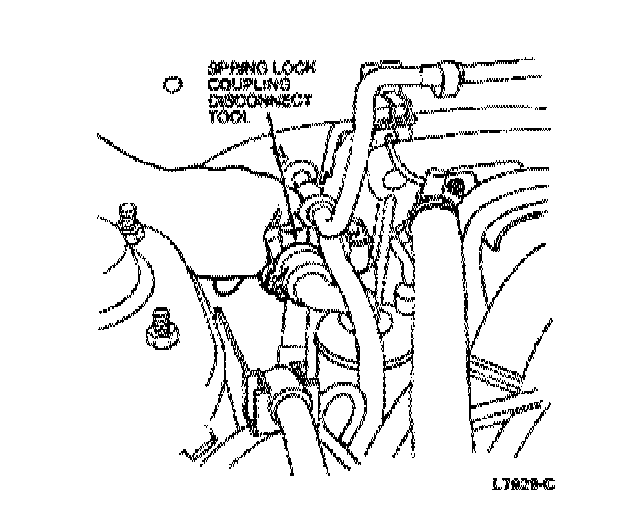
2. CAUTION:Plug all ports to prevent the entrance of dirt and moisture.
Disconnect the condenser to evaporator tube (19835) and the suction accumulator/drier inlet tube from the evaporator core at the bulkhead.
3. Disconnect the battery ground cable (14301).
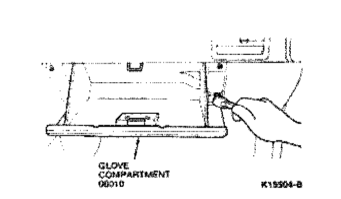
4. Remove the two hinge-to-instrument panel screws and remove the glove compartment (06010).
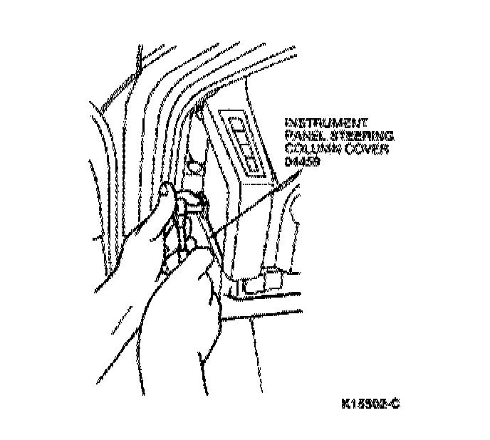
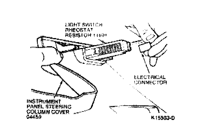
5. Detach the hood latch control handle and cable (16916) from the instrument panel steering column cover (04459).
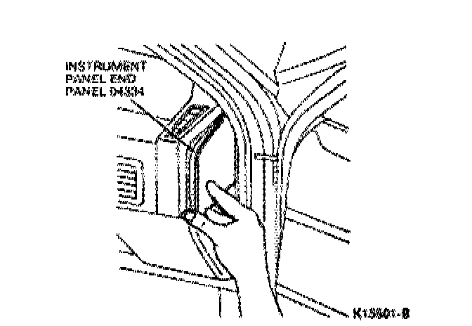
6. Carefully pry out both instrument panel end panels (04334).
7. Remove the four screws and the instrument panel steering column cover. Disconnect the light switch rheostat resistor electrical connector and the fog lamp switch electrical connector, if equipped.
8. Remove the four steering column shroud screws and the lower steering column shroud (3530)
9. Remove the four bolts securing the steering column to the instrument panel reinforcement (04545) and lower the steenng column
10. Disconnect thespeedometer cable (17260) from the speedometer head by reaching up behind the instrument cluster and squeezing the speedometer cable retainer.
11. Remove the shift console Refer to the removal and installation procedure in Section 01-12.
12. Disconnect the recirc/fresh vacuum hose harness.
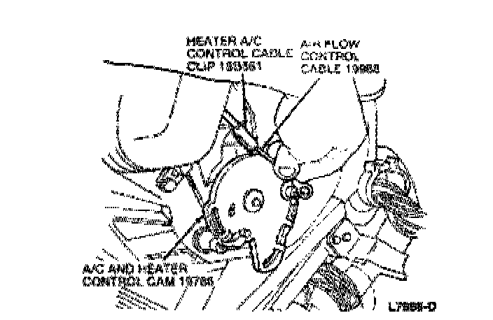
13. Disconnect the airflow control cable from the A/C and heater control cam (19788) and the heater A/C control cable clip (18B561).
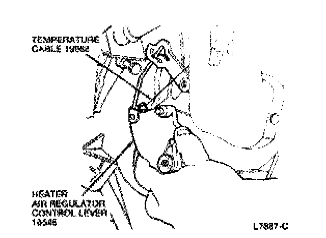
14. Disconnect the temperature cable from the heater air regulator control lever (18546) and the heater NC control cable clip.
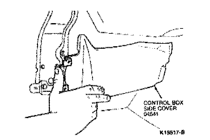
15. Remove the push pins and the LH and RH control box side covers.
16. Remove the four instrument panel reinforcement-to4loor pan bolts.
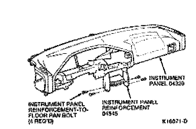
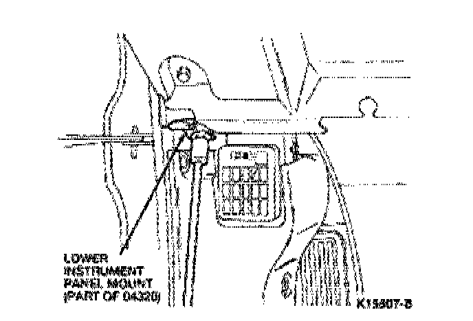
17. Remove the bolts from both of the lower instrument panel mounts.
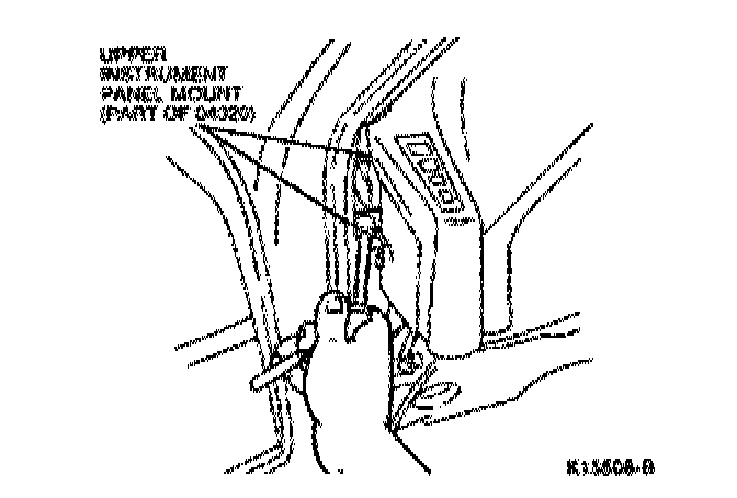
18. Remove the two bolts from both of the upper instrument panel mounts.
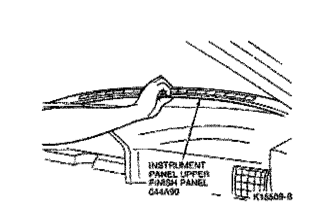
19. Remove the Torx screw and the instrument panel upper finish panel (044A90).
20. Remove the three upper instrument panel-to-upper cowl bolts.
21. Pull the instrument panel (04480) away from the bulkhead to access the A/C evaporator housing.
22. Disconnect the two electrical connectors from the heater blower motor switch resistor (18591).
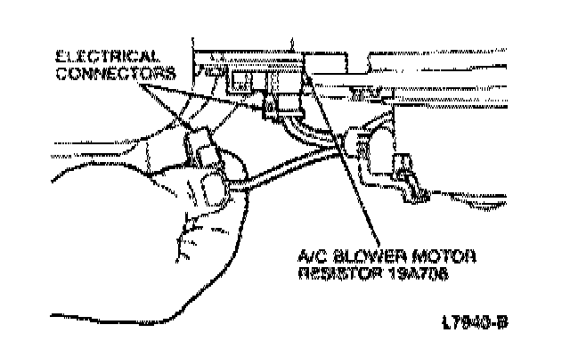
23. Disconnect the electrical connector from the A/C blower motor (19805).
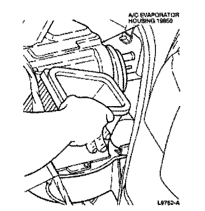
24. Loosen the A/C evaporator outlet duct clamp screw.
25. Remove the four A/C evaporator housing nuts and the A/C evaporator housing.
Installation
NOTE:Use new 0-rings lubricated with clean refrigerant oil
To install, reverse the removal procedure
Adjust the temperature cable and the airflow control cable. Adjustments
Leak test, evacuate, and charge the A/C system. Service and Repair